

What is FDTD?
1. Introduction


Finite-Difference Time-Domain (FDTD) solves Maxwell’s equations-which describe light- directly in the time domain on a discrete spatial grid. In contrast to ray tracing, mode solvers, or transfer-matrix approaches, FDTD makes no simplifying assumptions about propagation or modal structure. Instead, the electric and magnetic fields are advanced explicitly in time by discretising the curl equations-Ampère’s law and Faraday’s law-so that electromagnetic waves propagate, scatter, interfere, and diffract naturally throughout the simulation domain. This generality makes FDTD highly accurate and versatile, but also computationally demanding in terms of memory and runtime.
\[ \nabla \times \boldsymbol{H} = \sigma \boldsymbol{E} + \epsilon \frac{\partial \boldsymbol{E}}{\partial t}, \qquad \nabla \times \boldsymbol{E} = - \mu \frac{\partial \boldsymbol{H}}{\partial t}. \]
Because FDTD makes essentially no assumptions about propagation direction, device structure, or field behaviour, a single simulation can capture broadband response, diffraction and interference, near-field effects, sub-wavelength geometry, and transient electromagnetic phenomena within a single framework. This generality is what makes FDTD so powerful, but it also comes at a cost: the spatial grid must resolve the smallest physical length scale, the time step is tightly constrained by numerical stability, and three-dimensional simulations quickly become demanding in both memory and runtime, even for geometries that appear modest in size.
2. Why you should not use FDTD...
In most practical optical problems, FDTD should not be the first method you reach for. It is computationally intensive, and for many systems there are far more efficient approaches. Designing lens systems such as cameras or telescopes, modelling large-scale imaging setups, or tracing light through macroscopic optical assemblies is far better handled using ray tracing. Likewise, planar multilayer structures such as thin-film solar cells, OLED stacks, and optical coatings are much more efficiently treated using transfer-matrix methods. In these cases, FDTD adds significant computational cost without providing additional physical insight.
Most electromagnetic simulation methods ultimately originate from Maxwell’s equations. Techniques such as mode solvers and transfer-matrix methods are derived by introducing simplifying assumptions about geometry, dimensionality, or field structure in order to accelerate computation. These approximations are extremely powerful-but only when their underlying assumptions hold.
FDTD sits at the opposite end of this spectrum. It is extremely powerful, particularly for complex three-dimensional systems, irregular geometries, and problems where the field cannot be decomposed into simple modes or layers—such as photonic crystals, sub-wavelength structures, strongly scattering media, and near-field coupling. The price for this flexibility is computational cost, both in memory and runtime.
The key is to choose the right tool. Use reduced models when the physics allows it, and use FDTD when those assumptions break down. Its strength is flexibility and physical completeness; the trade-off is computational cost.
3. Maxwell’s equations behind FDTD
At its core, FDTD is very simple. You take Maxwell’s equations, expand them into their components for each spatial direction, and then solve those equations directly on a grid. There is no magic—the method is conceptually straightforward, and in many ways simpler than more involved numerical approaches such as drift–diffusion solvers. To begin, we expand Ampère’s law. In a linear medium with conductivity \(\sigma\), permittivity \(\epsilon\), and permeability \(\mu\), this can be written as:
\[ \sigma \boldsymbol{E} + \epsilon \frac{\partial \boldsymbol{E}}{\partial t} = \nabla \times \boldsymbol{H} = \begin{vmatrix} \hat{\boldsymbol{x}} & \hat{\boldsymbol{y}} & \hat{\boldsymbol{z}} \\ \frac{\partial}{\partial x} & \frac{\partial}{\partial y} & \frac{\partial}{\partial z} \\ H_x & H_y & H_z \end{vmatrix} \]
which can be expanded as
\[ \sigma E_x + \epsilon \frac{\partial E_x}{\partial t} = \frac{\partial H_z}{\partial y} - \frac{\partial H_y}{\partial z} \]
\[ \sigma E_y + \epsilon \frac{\partial E_y}{\partial t} = -\frac{\partial H_z}{\partial x} + \frac{\partial H_x}{\partial z} \]
\[ \sigma E_z + \epsilon \frac{\partial E_z}{\partial t} = \frac{\partial H_y}{\partial x} - \frac{\partial H_x}{\partial y} \]
Faraday’s law is given as
\[ -\sigma_m \boldsymbol{H} - \mu \frac{\partial \boldsymbol{H}}{\partial t} = \nabla \times \boldsymbol{E} = \begin{vmatrix} \hat{\boldsymbol{x}} & \hat{\boldsymbol{y}} & \hat{\boldsymbol{z}} \\ \frac{\partial}{\partial x} & \frac{\partial}{\partial y} & \frac{\partial}{\partial z} \\ E_x & E_y & E_z \end{vmatrix} \]
which can be expanded to give:
\[ -\sigma_m H_x - \mu \frac{\partial H_x}{\partial t} = \frac{\partial E_z}{\partial y} - \frac{\partial E_y}{\partial z} \]
\[ -\sigma_m H_y - \mu \frac{\partial H_y}{\partial t} = -\frac{\partial E_z}{\partial x} + \frac{\partial E_x}{\partial z} \]
\[ -\sigma_m H_z - \mu \frac{\partial H_z}{\partial t} = \frac{\partial E_y}{\partial x} - \frac{\partial E_x}{\partial y} \]
The equations highlighted in blue and red are the definition of FDTD and form the heart of the method. There is nothing more complicated than this. Everything else is implementation: replacing derivatives with finite differences, choosing boundary conditions, defining light sources (excitations), extracting results using detectors, and writing efficient (often parallel) code to evolve the fields in time. These additional components make a practical FDTD solver more complex, but they do not change the underlying simplicity of the core method.
4. A toy 1D FDTD example
To demonstrate how simple FDTD is—both conceptually and in implementation—we now reduce the full equations to a one-dimensional toy model that can be implemented in a few tens of lines of MATLAB or Python. The goal here is not to change the physics, but to strip away unnecessary complexity so that the structure of the method is completely transparent.
To do this, we consider variation only along the \(x\)-direction and explicitly set the remaining spatial derivatives to zero: \[ \frac{\partial}{\partial y} = 0, \qquad \frac{\partial}{\partial z} = 0. \] This leaves a transverse electromagnetic system with electric field \(E_z(x,t)\) and magnetic field \(H_y(x,t)\).
Under these assumptions, Maxwell’s curl equations reduce to
\[ \epsilon \frac{\partial E_z}{\partial t} = \frac{\partial H_y}{\partial x} \]
\[ \mu \frac{\partial H_y}{\partial t} = \frac{\partial E_z}{\partial x}. \]
These are the core continuous equations for the 1D case. However, in this form they cannot be solved directly on a computer. To do that, we replace the derivatives with finite differences on a discrete grid. This is the essence of the method: see finite differences for a general overview.
Introducing a spatial grid \(x_i = i\Delta x\) and time steps \(t^n = n\Delta t\), and using the standard staggered (leapfrog) arrangement, the update equations become
\[ E_z^{n+1}(i) = E_z^n(i) + \frac{\Delta t}{\epsilon(i)\,\Delta x} \left[ H_y^{n+\frac{1}{2}}\!\left(i+\frac{1}{2}\right) - H_y^{n+\frac{1}{2}}\!\left(i-\frac{1}{2}\right) \right] \]
\[ H_y^{n+\frac{1}{2}}\!\left(i+\frac{1}{2}\right) = H_y^{n-\frac{1}{2}}\!\left(i+\frac{1}{2}\right) + \frac{\Delta t}{\mu\,\Delta x} \left[ E_z^n(i+1) - E_z^n(i) \right]. \]
This is already the full FDTD method in its simplest form. The electric field is updated from spatial differences in the magnetic field, and the magnetic field is updated from spatial differences in the electric field, with the two fields leapfrogging in time.
For a non-magnetic medium, \(\mu = \mu_0\), and the permittivity is related to the refractive index by
\[ \epsilon(x) = \epsilon_0 n(x)^2. \]
This means a refractive-index step is introduced simply by changing \(\epsilon\) across the grid. In the example below, we consider a medium which transitions from \(n=1\) to \(n=3\), so that a pulse launched from the left partially reflects and partially transmits at the interface.
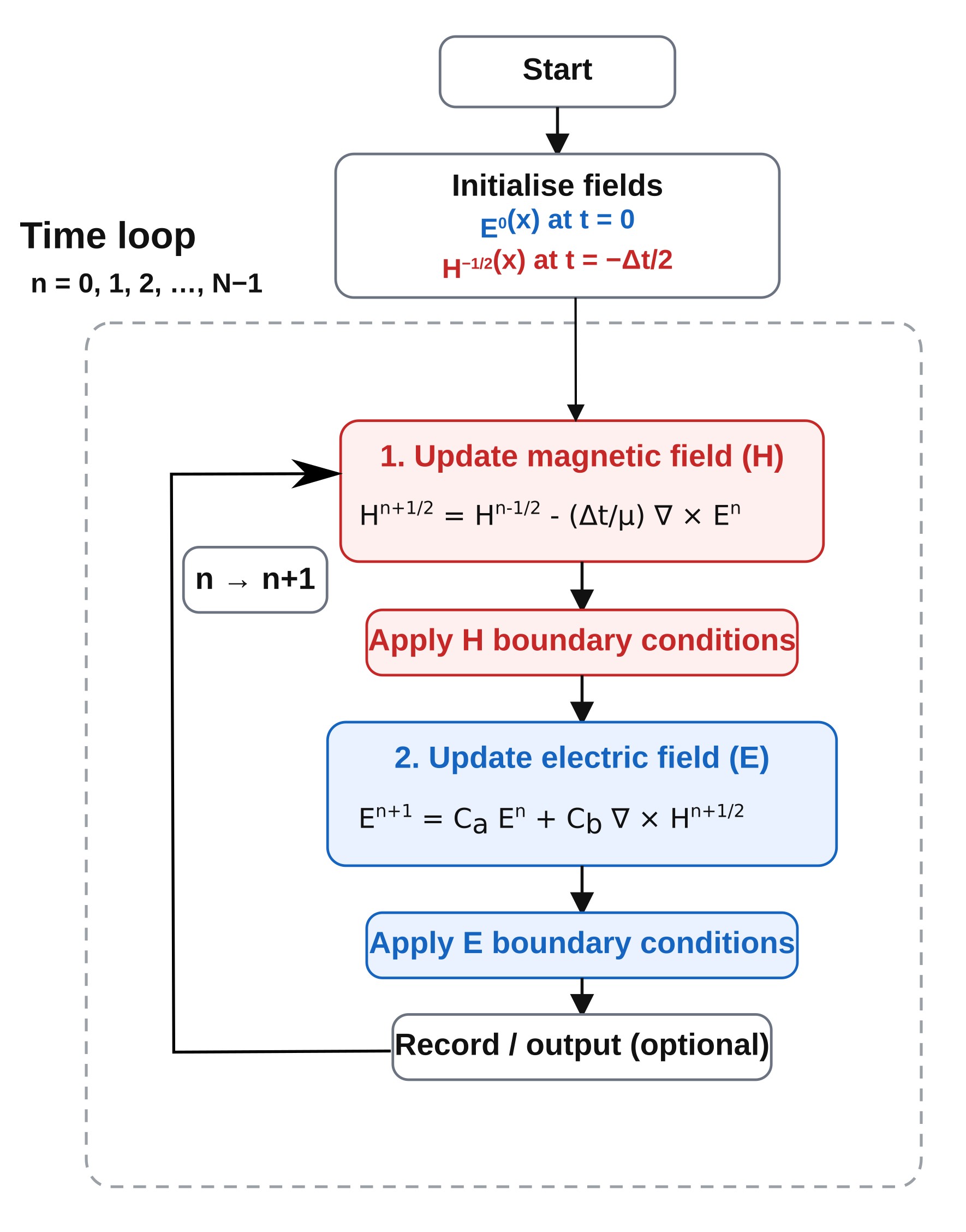
In practice, the equations above are simply placed inside a time-stepping loop: the magnetic field is updated from the electric field, boundary conditions are applied, then the electric field is updated from the magnetic field, and the process repeats. The fields are staggered in time so that they leapfrog forward in a simple, explicit scheme, with each update depending only on local neighbouring values. This is shown schematically in ??, and is essentially all the computer is doing at each time step.
5. A toy 1D FDTD example in Matlab/Python
The same one-dimensional FDTD scheme can be implemented in just a few tens of lines of code. Below are equivalent implementations in MATLAB and Python. Both launch a Gaussian pulse and show reflection from a refractive-index step.
MATLAB
clear;
clc;

% Physical constants
c0   = 299792458;
mu0  = 4*pi*1e-7;
eps0 = 1/(mu0*c0^2);

% Grid
Nx = 400;
dx = 20e-9;
dt = dx/(2*c0);

% Material profile
n = ones(1, Nx);
n(220:end) = 3.0;
eps_r = n.^2;

% Fields
Ez = zeros(1, Nx);
Hy = zeros(1, Nx-1);

% Source
source_pos = 80;
t0 = 40;
spread = 12;

Nt = 600;

figure;

for t = 1:Nt

    % Update H
    for i = 1:Nx-1
        Hy(i) = Hy(i) + (dt/(mu0*dx))*(Ez(i+1) - Ez(i));
    end

    % Update E
    for i = 2:Nx-1
        Ez(i) = Ez(i) + (dt/(eps0*eps_r(i)*dx))*(Hy(i) - Hy(i-1));
    end

    % Source
    Ez(source_pos) = Ez(source_pos) + exp(-((t - t0)/spread)^2);

    % Simple absorbing boundaries
    Ez(1)   = Ez(2);
    Ez(end) = Ez(end-1);

    % Plot every few steps
    if mod(t,5) == 0
        plot(1:Nx, Ez, 'b', 'LineWidth', 1.5);
        hold on;
        plot([220 220], [-1.5 1.5], '--r', 'LineWidth', 1.0);
        hold off;
        xlabel('Grid index');
        ylabel('E_z');
        title(['1D FDTD pulse reflecting from an index step, t = ', num2str(t)]);
        axis([1 Nx -1.5 1.5]);
        grid on;
        drawnow;
    end
end
Python (NumPy / Matplotlib)
import numpy as np
import matplotlib.pyplot as plt

c0 = 299792458.0
mu0 = 4.0e-7 * np.pi
eps0 = 1.0 / (mu0 * c0**2)

Nx = 400
dx = 20e-9
dt = dx / (2 * c0)

n = np.ones(Nx)
n[220:] = 3.0
eps_r = n**2

Ez = np.zeros(Nx)
Hy = np.zeros(Nx - 1)

source_pos = 80
t0 = 40
spread = 12

Nt = 600

plt.ion()
fig, ax = plt.subplots()

for t in range(Nt):

    Hy += (dt / (mu0 * dx)) * (Ez[1:] - Ez[:-1])
    Ez[1:-1] += (dt / (eps0 * eps_r[1:-1] * dx)) * (Hy[1:] - Hy[:-1])

    Ez[source_pos] += np.exp(-((t - t0) / spread) ** 2)

    Ez[0] = Ez[1]
    Ez[-1] = Ez[-2]

    if t % 5 == 0:
        ax.clear()
        ax.plot(Ez)
        ax.axvline(220, linestyle='--')
        ax.set_xlim(0, Nx)
        ax.set_ylim(-1.5, 1.5)
        plt.pause(0.01)

plt.ioff()
plt.show()
6. Running the simulation
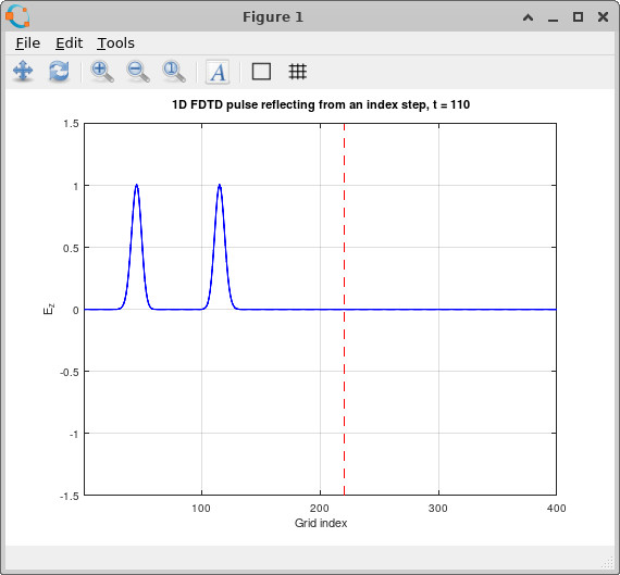
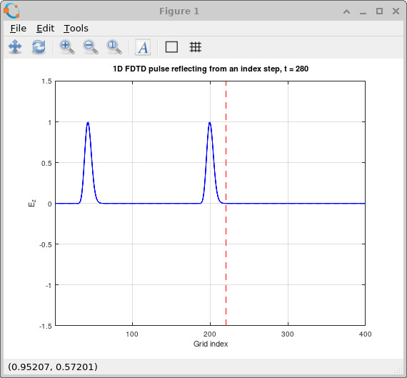
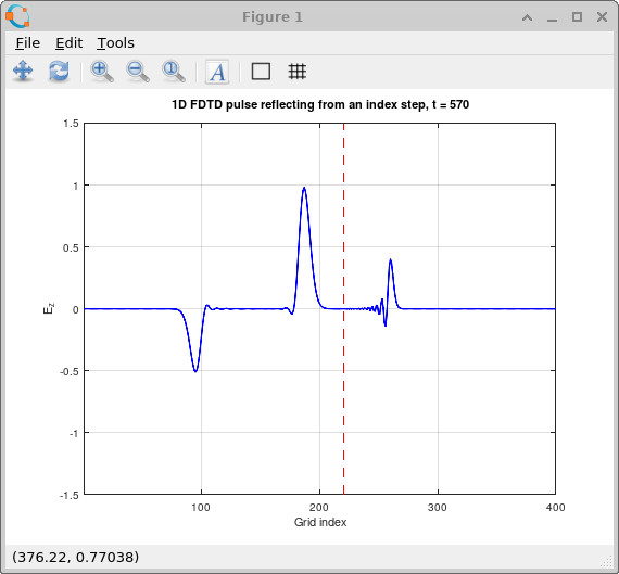
The behaviour of the simulation is shown in ??–??. Initially, the Gaussian pulse propagates cleanly through the \(n=1\) region. As it reaches the index step, the field splits into two components: a reflected pulse travelling back into the low-index region and a transmitted pulse entering the higher-index region. Because the refractive index increases to \(n=3\), the transmitted wave slows down and compresses in wavelength, while the reflected component retains the original propagation characteristics. This is exactly the expected physical behaviour and demonstrates that even this minimal implementation captures the essential physics of wave propagation, reflection, and transmission.
11. Where to go next
The MATLAB and Python examples above show how simple FDTD is in principle, but they are only toy implementations. In practice, realistic optical simulations require large grids, long run times, and careful handling of boundaries and sources. To push FDTD to useful, real-world problems, you need a solver that is highly optimised, parallelised, and capable of running on both CPUs and GPUs.
This is exactly what OghmaNano provides: a full 3D FDTD solver written in C with OpenCL acceleration, allowing the same model to run seamlessly on multi-core CPUs or GPUs. Rather than building your own solver from scratch, you can take the ideas shown here and immediately apply them to realistic photonic structures, devices, and wave-optics problems.
To get started, you can explore the FDTD in OghmaNano page for an overview of capabilities, revisit what FDTD is or the full mathematical derivation, or move directly to practical setup using light sources, boundary conditions, and detectors.
A wide range of ready-to-run examples are also available, including free-space propagation, double-slit interference, photonic crystal waveguides, Bragg gratings, Fabry–Pérot cavities, tilted waveguide facets, tapered structures, Mach–Zehnder devices, ring resonators, and anti-reflection coatings.
In short: the core method is simple, as shown above—but OghmaNano is designed to take that simplicity and scale it up into a practical, high-performance tool for real optical simulation.