CELIV Simulation on Perovskite Solar Cells: Part B
Step 1: Eding the ramp rate
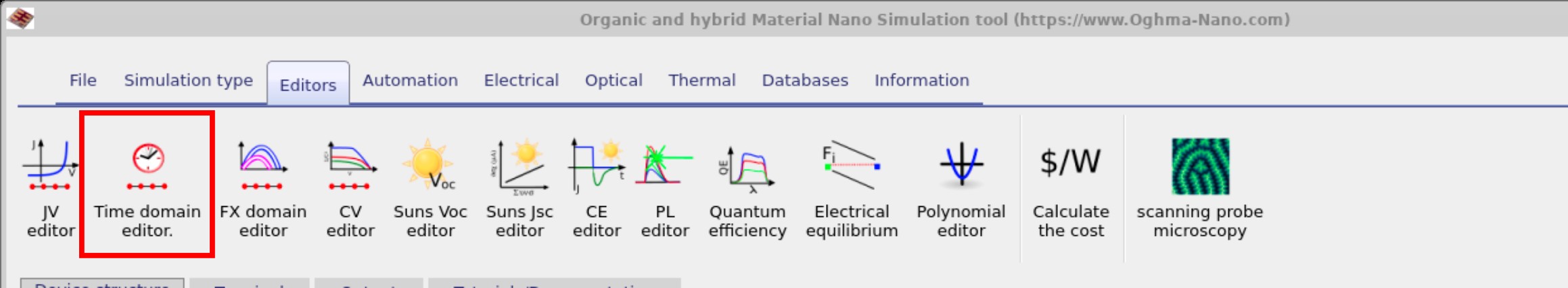
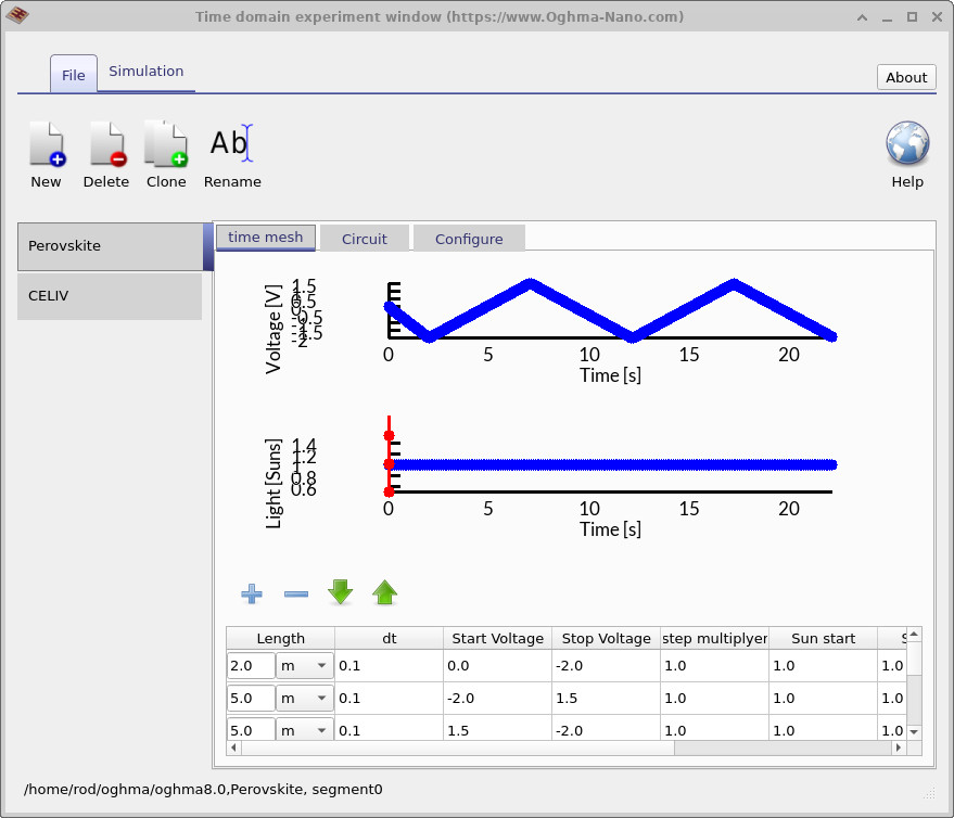
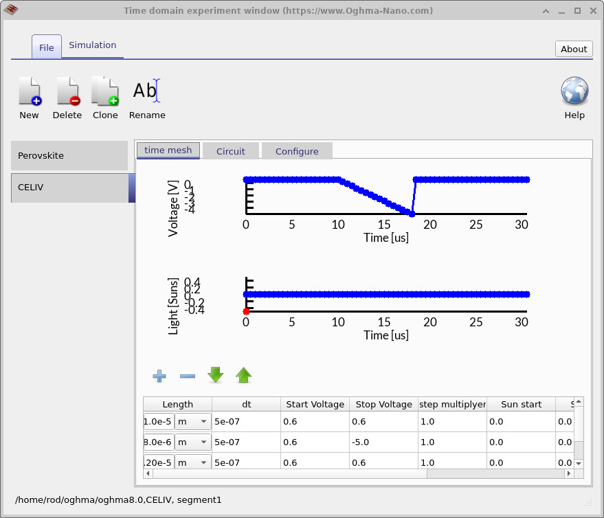
The CELIV experiment relies on the Time Domain Editor. Time-domain simulations are configured using this tool, which can be accessed from the Editors window by clicking the Time Domain Editor button (??). The first tab presents the default time-domain J–V sweep used to simulate hysteresis in perovskite devices (??). In this configuration the voltage starts at 0 V, sweeps down to a negative bias, then up to a positive bias — a standard setup for time-domain J–V hysteresis simulations. However, for CELIV we are not interested in the hysteresis sweep, but rather in the extraction transient. By clicking on the CELIV tab, you can switch to the CELIV experiment setup (??). Here, the simulation is configured with an initial pre-bias of +0.6 V, followed by a linear sweep down to –5 V, and then an abrupt return to the starting voltage. The experiment is also defined under dark conditions (no illumination). Note that tab names in the Time Domain Editor are fully editable, so you can rename them as needed. The parameters of the voltage program can be modified directly using the table at the bottom of the window.
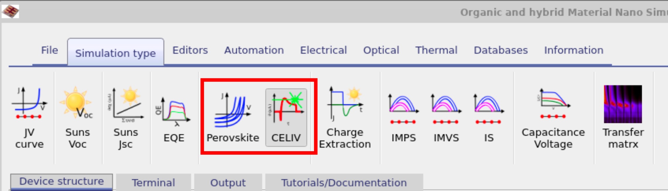
From the main OghmaNano window, navigate to the Simulation type ribbon (??). You will see two icons associated with the time-domain editor: the Perovskite scan and the CELIV scan. These are directly linked to the waveforms defined earlier in the Time Domain Editor. If the CELIV button is selected, the solver will run a CELIV transient; if the Perovskite button is active, the solver will instead perform the time-domain J–V sweep as demonstrated previously. It is important to note that these voltage sweeps are always applied to the active contact defined in the Contact editor. The same principle applies to any device type (for example OFETs, OLEDs, or diodes). As an exercise, go back to the Time Domain Editor under the CELIV tab and change the stop voltage from –5 V to –6 V. Then re-run the simulation and examine how the extraction transient is modified. Further guided tasks below will help you deepen your understanding of CELIV analysis.
📝 Try it yourself:
- Open the Time Domain Editor and switch to the CELIV tab.
- Change the Stop Voltage from –5 V to –10 V.
- Re-run the simulation and compare the new CELIV transient with the original. How does the extraction peak shift in time and amplitude?
- Adjust the Ramp Length to make the voltage sweep slower or faster. Observe how this affects the peak position and width.
- In the Electrical parameters editor, reduce the carrier mobility by an order of magnitude. Run the CELIV again — how does the lower mobility change the peak time?
- Now increase the mobility value (e.g. double it) and note the effect. Does the extraction peak move earlier as expected?
- In the optical ribbon of the main window, increase the Light intsnity value to simulate higher/lower illumination. Observe how stronger generation increases the transient peak height.
✅ Expected outcomes
- Stop Voltage: More negative stop voltage increases the extraction field, leading to a slightly higher and sharper peak.
- Ramp Length: A slower sweep (longer ramp) shifts the peak to later times and broadens it; a faster sweep makes the peak earlier and narrower.
- Mobility: Lower mobility delays the peak (larger tmax), while higher mobility shifts the peak earlier. This follows directly from the CELIV equation.
- Light Intensity: Increasing illumination raises the peak amplitude since more carriers are generated. Reducing illumination suppresses the peak, and at very low light the extraction signal may be hard to separate from the capacitance baseline.
These trends are consistent with CELIV theory and provide a way to validate both your simulation settings and your physical intuition.
👉 Next steps:
- Return to the perovskite solar cell simulation guide for the full tutorial overview.