200 mm Prime Lens Tutorial (Part A): Load, Inspect, and Run a Baseline Ray Trace
1. Introduction
A prime lens is a lens with a fixed focal length, in contrast to a zoom lens whose focal length varies continuously (see ??). Prime lenses are widely used in photography and imaging systems because a design can be optimized around one focal length: compared with a zoom of similar specification, a prime is often optically simpler, typically supports a wider usable aperture, and can deliver cleaner off-axis performance for the same size and cost. In this tutorial we use a 200 mm prime as a geometry-first “read the rays” exercise: the goal is not a merit function, but to learn how to spot incorrect stop placement, unintended clipping, and mis-positioned detector planes quickly.
In this tutorial we use a 200 mm prime lens to demonstrate how to inspect a multi-element photographic lens in 3D, run a baseline ray trace, and interpret the output qualitatively. The goal is not to “score” the lens with a merit function; it is to learn how to read the geometry and ray paths so you can quickly spot clipping, misplacement of the stop, and off-axis sensitivity.
The workflow in this tutorial mirrors standard practice in professional optical design: before any optimisation or quantitative merit functions are introduced, a lens model is first validated geometrically by inspecting ray paths, stop placement, and detector behaviour. If a model fails these checks, numerical metrics are meaningless.
2. Loading the 200 mm prime lens example
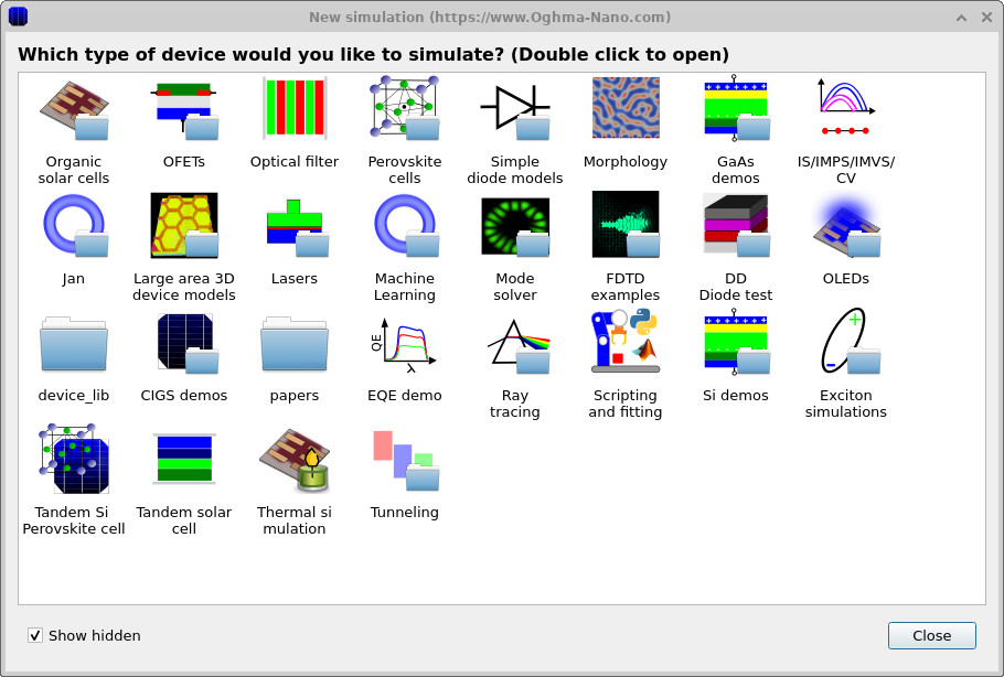
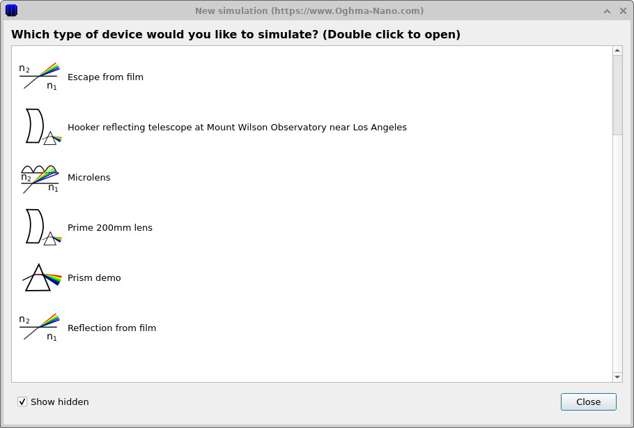
From the main window click New simulation. This opens the simulation library (??). Double-click Ray tracing to enter the optics examples (??), then select Prime 200mm lens (or 200mm prime lens) and choose a working directory (for example, your home folder).
3. Orienting yourself in the 3D scene, running a baseline ray trace
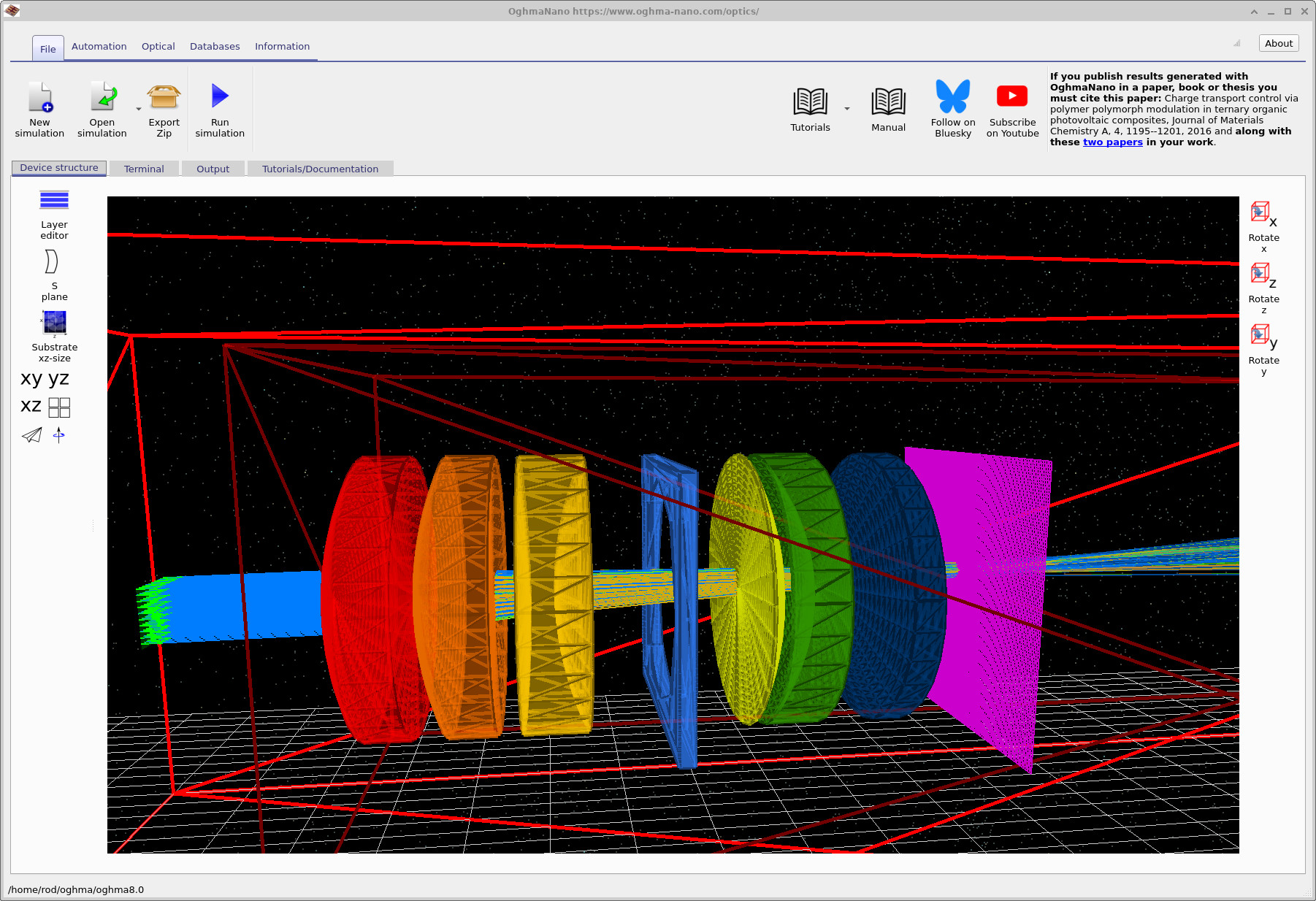
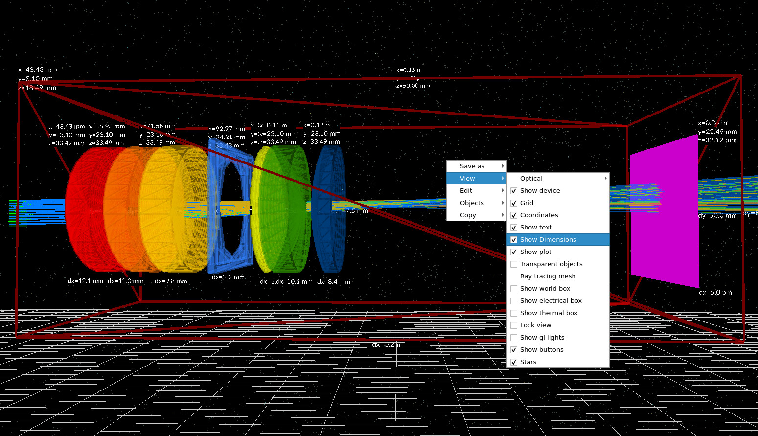
After loading, the Optical Workbench should open in a view similar to ??. The optical axis runs from left to right. On the left you should see one or more light sources (green), in the middle the lens elements (coloured glass surfaces), and on the right a detector plane (purple).
For this design you can think in terms of “front optics” plus a “rear section” near the detector: the key point for Part A is simply to identify (i) the main lens elements, (ii) the aperture/stop object, and (iii) the detector plane. (If you are curious: the published telephoto designs this demo is based on use a movable objective section and a rear correcting element fixed relative to the film/sensor plane.)
Use the mouse to explore: drag on the black background to rotate the view and inspect element spacing. The goal is to become confident you can visually locate the stop and the detector before running anything.
Click Run simulation (the blue triangle in the main toolbar). When the run completes you should see rays propagating from the sources, through the full lens stack, and onto the detector plane (see ??).
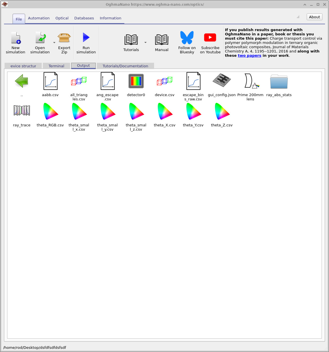
4. Locating and opening the key outputs
Switch to the Output tab. You should see a detector folder (typically detector0) and
associated ray-tracing outputs (example in
??).
Each detector has its own output directory: open detector0 (it is drawn with a “camera/CCD” icon).
detector0.
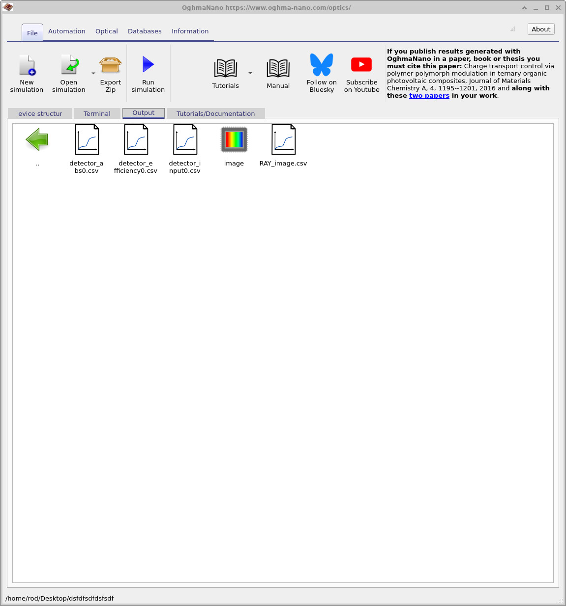
detector0. Open RAY_image.csv.
After opening detector0, you should see files including RAY_image.csv
(example in ??).
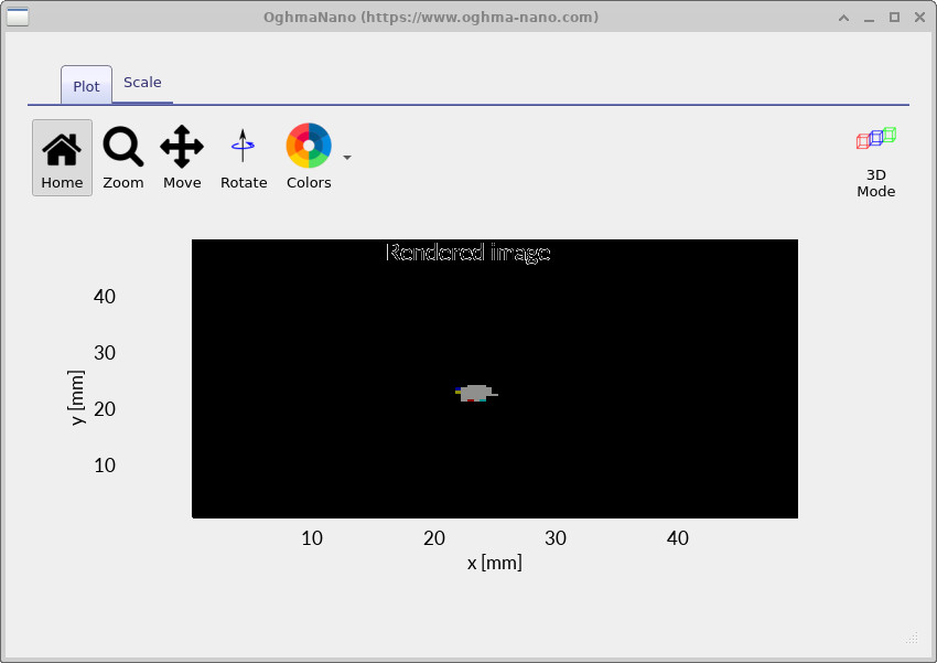
Double-click RAY_image.csv to view the detector image.
In a real camera, this detector plane corresponds to the sensor/film plane: i.e. in a modern digital camera,
you would be forming this image on a CMOS/CCD sensor placed at that plane.
A quick focus sanity-check (move the detector plane)
The fastest way to build intuition is to move the detector plane rather than moving lens elements. Conceptually, this is like moving the sensor forward/backward relative to the lens and watching how the blur changes. Your goal is to find the detector position that gives the smallest spot on the detector (by eye).
First, enable on-screen dimensions. Right-click on the black background, choose View, and enable
Show dimensions (see
??).
You should now see the x/y/z positions of objects and thicknesses/lengths (shown as dx, etc.).
Now move the detector plane forwards and backwards along the optical axis and observe how the spot changes. For a clear demonstration, move it to extremes (clearly too far forward, then clearly too far back), and then hunt for the position where the spot is smallest. You can either re-run the simulation after each change, or (for a quick qualitative check) simply observe how the ray intersections shift on the detector plane.
Is “best focus” the position with the smallest spot? For this tutorial: yes - treat the minimum footprint as the best-focus condition. (Later, metrics such as RMS spot radius formalize exactly this idea, but you do not need them to learn the geometry-first workflow.)
If you want a numerical value for “sensor-to-last-element distance”, you can estimate it directly from the on-screen geometry:
read the x coordinate of the final lens element (its reference position), add its thickness dx,
then subtract from the x coordinate of the detector plane. This gives an approximate spacing between the rear
surface of the last element and the detector plane. Repeat this at your visually best-focus position and record the value.
What you can now do (Part A)
- Load and navigate the 200 mm prime lens demo in the Optical Workbench.
- Run a baseline ray trace and confirm rays reach the detector plane.
- Open the outputs and view
detector0/RAY_image.csvas a quick sanity check. - Find best focus by eye by moving the detector plane and looking for the minimum spot.
Common checks if the output looks “wrong”
- Confirm the detector plane is behind the lens group and facing the beam.
- Reduce ray density if the 3D view becomes visually cluttered.
- Check that you opened the correct detector folder (the magenta plane in the 3D scene).
- If moving the detector does not change the spot size at all, re-check that rays actually intersect the detector.
👉 Next steps: Continue to Part B to identify chief and marginal rays, diagnose clipping/vignetting by eye, and build a “pre-metric” lens sanity-check workflow.
For an overview of optical systems and ray-tracing simulations, see Optical systems and ray tracing overview.