OghmaNano
Multiphysics simulation platform for optoelectronic devices and photonic systems DOWNLOADQuick Start guide
JV editor (Steady state simulation editor)
1. Inputs
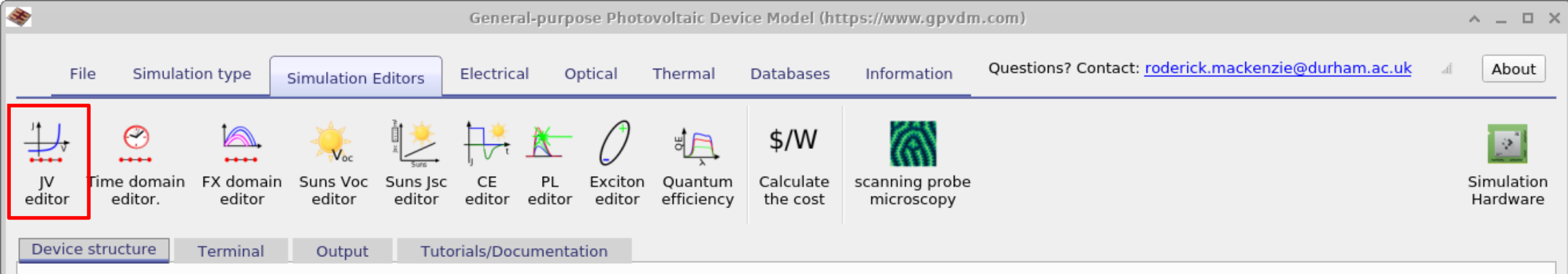
If you click the JV editor icon in the simulation editors ribbon (??),
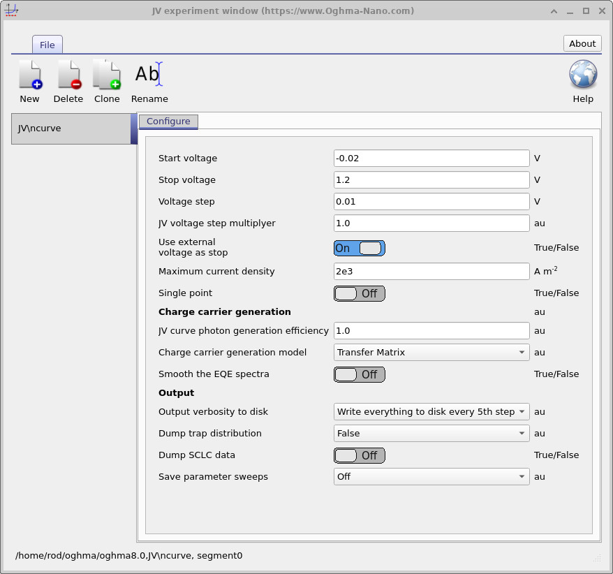
the JV editor window will open (??). The JV editor is used to configure steady-state current–voltage simulations.
It applies a voltage ramp from a defined start voltage to a stop voltage, regardless of whether the device
is a solar cell, an OFET, or another structure.
Opening the JV editor from the simulation editors ribbon.
You can set the start voltage, stop voltage, and step size. The JV voltage step multiplier
scales the step size after each increment. The default is 1.0 (no growth).
Setting this multiplier slightly above 1.0 can reduce the number of steps and speed up the simulation,
but values much greater than 1.05 may cause convergence issues.
JV editor window for configuring steady-state current–voltage simulations.
Parameter
Description
Start voltage
Beginning bias of the voltage ramp (V).
Stop voltage
Final bias of the voltage ramp (V).
Voltage step
Increment between successive bias points (V).
JV voltage step multiplier
Scales the step size after each point. Values > 1 increase the step as the sweep progresses (useful for large ranges); very large values may affect convergence.
Use external voltage as stop
Chooses the stopping criterion. When On, uses the external device voltage (after series/shunt resistance). When Off, uses the internal diode voltage.
Maximum current density
Terminates the sweep when current density reaches this threshold (A·m−2).
Single point
Computes a single operating point instead of a full JV sweep.
JV curve photon generation efficiency
Multiplier applied to the optical generation rate; can account for geminate recombination.
Charge carrier generation model
Selects the optical solver (e.g., Transfer Matrix, Ray Tracing).
Smooth the EQE spectra
Applies smoothing to EQE before use (used in certain 2D OFET simulations).
Output verbosity to disk
Controls snapshot writing (bands, carriers, generation rates). Write nothing, key results only, everything, or everything every nth step.
Dump trap distribution
Writes trap density-of-states profile to disk.
Save parameter sweeps
Saves summary metrics (average recombination, carrier densities, trapped carriers) in the sweep directory.
2. Outputs
Simulation files
Files produced by the JV simulation
File name
Description
Notes
charge.dat
Charge density vs. voltage
jv.dat
Current–voltage curve
k.csv
Recombination constant k
sim_info.dat
Simulation summary (calculated \(V_{oc}\), \(J_{sc}\), etc.); see
§4.1.4
Simulation directories
Directories written by the JV simulation
Directory
Description
Notes
snapshots/
Position-dependent data per simulation step for key device parameters (e.g., conduction band, valence band, potential, carrier densities, generation and recombination rates).
sweep/
Spatially integrated (device-averaged) metrics as a function of simulation step (e.g., total/average recombination rate, average carrier density, trapped carrier density).
These outputs can be enabled by adjusting Output verbosity to disk (and, for aggregated metrics, enabling Save parameter sweeps) in the simulation editor.
sim_info.dat
This is a json file containing all key simulation metrics such as \(J_{sc}\),
\(V_{oc}\), and example sim_info.dat file is given below: