OghmaNano
Multiphysics simulation platform for optoelectronic devices and photonic systems DOWNLOADQuick Start guide
Capacitance voltage editor
Experimentally capacitance voltage (CV) measurements are a useful way to determine doping within a device. In
OghmaNano CV measurements use a cut down version of frequency domain simulation tool described above.
2. Inputs
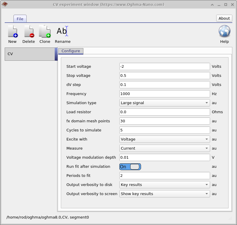
Capacitance–voltage (CV) editor — configure CV simulations by defining voltage sweep parameters, excitation, frequency, and output verbosity.
Parameter
Description
Start voltage
The voltage at which the CV experiment begins.
Stop voltage
The voltage at which the CV experiment ends.
dV step
Increment between voltage points in the sweep.
Frequency
Frequency of the AC perturbation (Hz). Example: 1000 Hz.
Simulation type
Defines the simulation regime. Should always be set to Large signal.
Load resistor
Defines external load resistance (e.g., 50 Ω for oscilloscope input).
fx domain mesh points
Number of mesh points per sinusoidal period, since large-signal mode explicitly simulates the waveform.
Cycles to simulate
Total number of AC cycles to simulate (e.g., 5 periods).
Excite with
Signal used to excite the device (e.g., Voltage).
Measure
Quantity recorded from the device response (e.g., Current).
Voltage modulation depth
Perturbation amplitude applied on top of the DC bias (V).
Run fit after simulation
If enabled, fits the simulated waveform after execution.
Periods to fit
Number of cycles (from the end of the simulation) used for fitting and extracting frequency domain information. Example: last 2 cycles out of 5.
Output verbosity to disk
Controls how much simulation data is written to disk; higher verbosity slows down simulation.
Output verbosity to screen
Controls the level of detail printed to the screen; lower verbosity speeds up execution.