The Step Editor: periodic object placement in OghmaNano
1. Introduction
Many photonic and electronic device structures are inherently periodic. A DFB (distributed feedback) grating requires a precisely spaced array of ridges or slots. A photonic crystal is built from a regular lattice of dielectric objects. A plasmonic metasurface consists of repeated resonator elements at sub-wavelength spacings. Constructing these structures object by object would be impractical, so OghmaNano provides a step editor that takes a single object and automatically generates copies of it at specified positions in 3D space.
An important property of this system is that every copy shares the same optical and electrical parameters as the original. The copies are not independent objects — they are a cluster of exact replicas, all inheriting the material assignments, layer properties, and optical constants of the parent object. This makes it straightforward to modify the entire periodic structure by editing only the original.
The step editor offers three modes of increasing complexity: a basic step mode for simple uniform arrays, a crystal mode for structures defined by primitive lattice vectors, and a Lua scripting mode for fully arbitrary point distributions.
2. Accessing the step editor
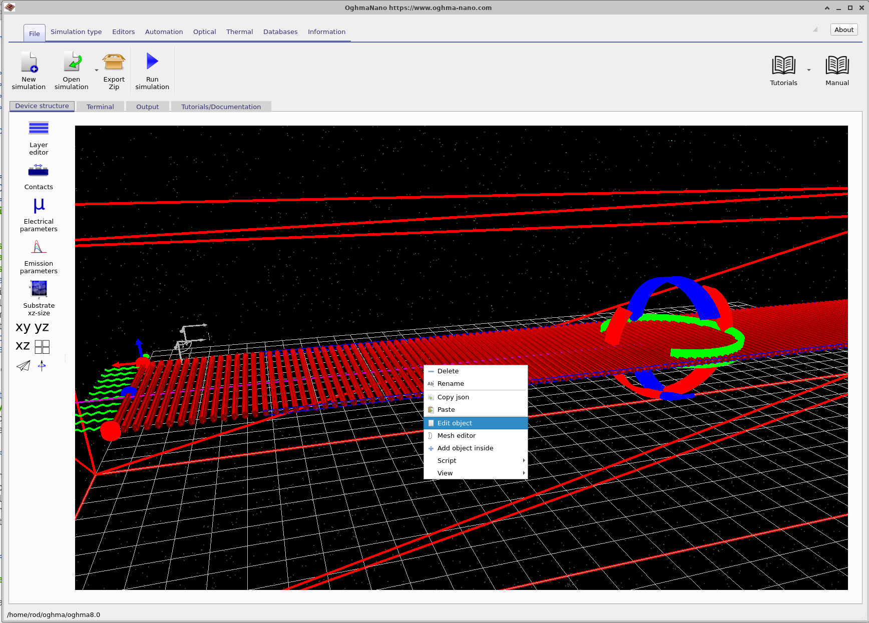
To access the step editor, start from the main OghmaNano simulation window (??). Right-click on the object you wish to replicate and select Edit object from the context menu. This opens the object editor, shown in ??.
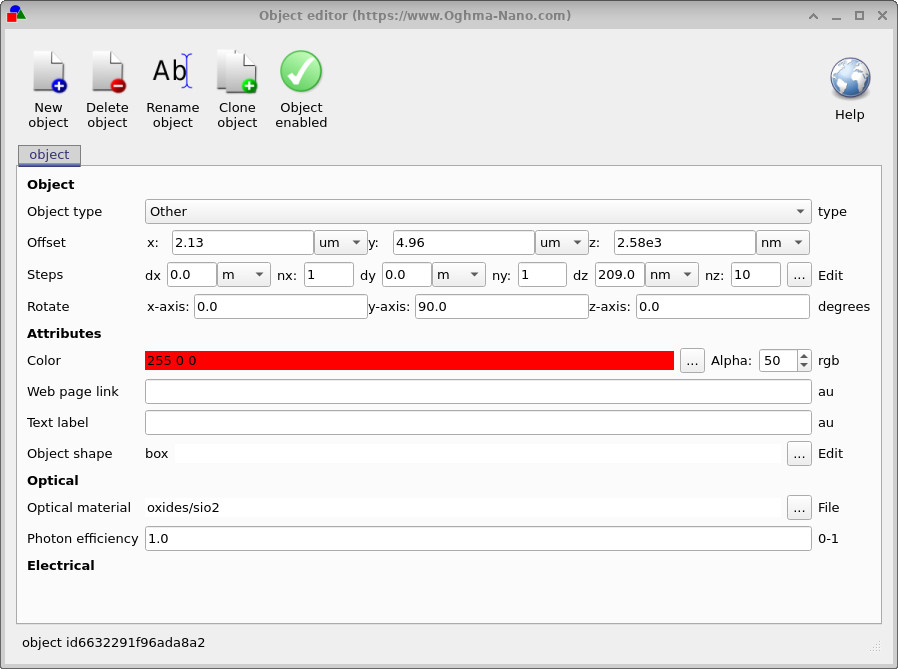
In the object editor, locate the Steps row. This row displays the current step parameters — the displacement (dx, dy, dz) between copies and the number of copies (nx, ny, nz) in each direction. Click the … Edit button at the right-hand end of the Steps row to open the step editor window.
3. Basic step mode
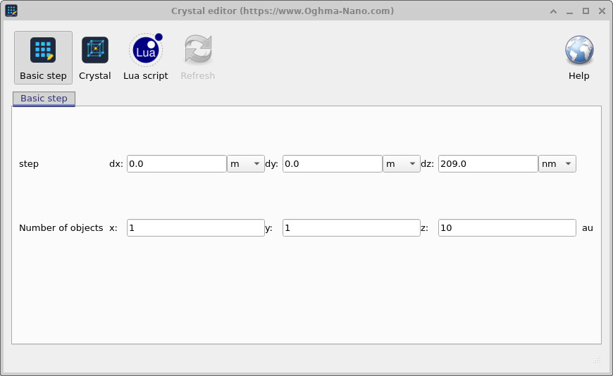
The step editor opens in Basic step mode by default, as shown in ??. This mode is the simplest way to create a 1D, 2D, or 3D array of objects. It takes a single step vector (dx, dy, dz) and tiles the object that many times along each axis. The fields are:
- step dx, dy, dz — the displacement between successive copies in each direction.
- Number of objects x, y, z — the number of copies to place along each axis.
For example, to create a 1D grating of 10 elements spaced 209 nm apart along z, set dz = 209 nm, nz = 10, and leave dx and dy at zero. This is the configuration shown in ??, which corresponds to a simple DFB grating period.
add_point(). Click Refresh to update the 3D view.
4. Crystal lattice mode
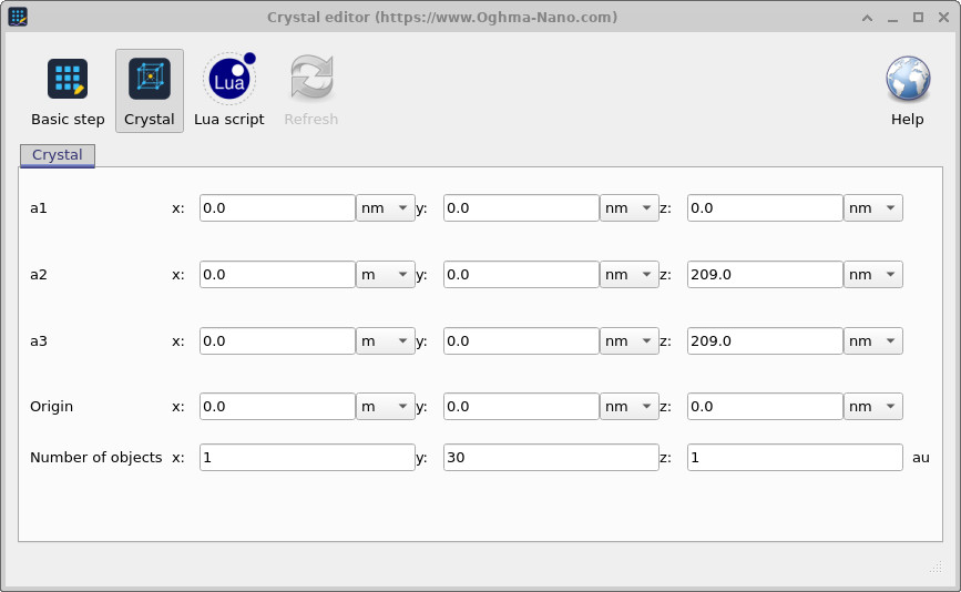
For structures with non-orthogonal or non-uniform periodicity, click the Crystal button in the step editor toolbar to switch to crystal mode (??). This mode defines the periodic arrangement using three primitive lattice vectors a1, a2, and a3 — the same formalism used in crystallography to describe a Bravais lattice.
Each object position is computed as:
\[ \mathbf{r}_{ijk} = \mathbf{r}_0 + i\,\mathbf{a}_1 + j\,\mathbf{a}_2 + k\,\mathbf{a}_3 \]
where i, j, k are integer indices running from 0 to nx−1, ny−1, nz−1 respectively, and r₀ is the origin. By choosing a1, a2, a3 appropriately, any Bravais lattice can be constructed — simple cubic, face-centred cubic, body-centred cubic, hexagonal, or any custom non-orthogonal arrangement.
5. Lua scripting mode
For fully arbitrary point distributions — spirals, helices, quasicrystals, or any geometry that cannot be expressed as a simple lattice — the step editor provides a Lua scripting interface, accessible by clicking the Lua script button (??).
Two built-in functions are available in this context:
clear_points()— removes all previously defined points.add_point(x, y, z)— places a copy of the object at position (x, y, z) in metres.
Any valid Lua code can be used between these calls, including loops, conditionals, trigonometric
functions, and random number generation via math.random(). After editing the script,
click Refresh to regenerate the point distribution and update the 3D view.
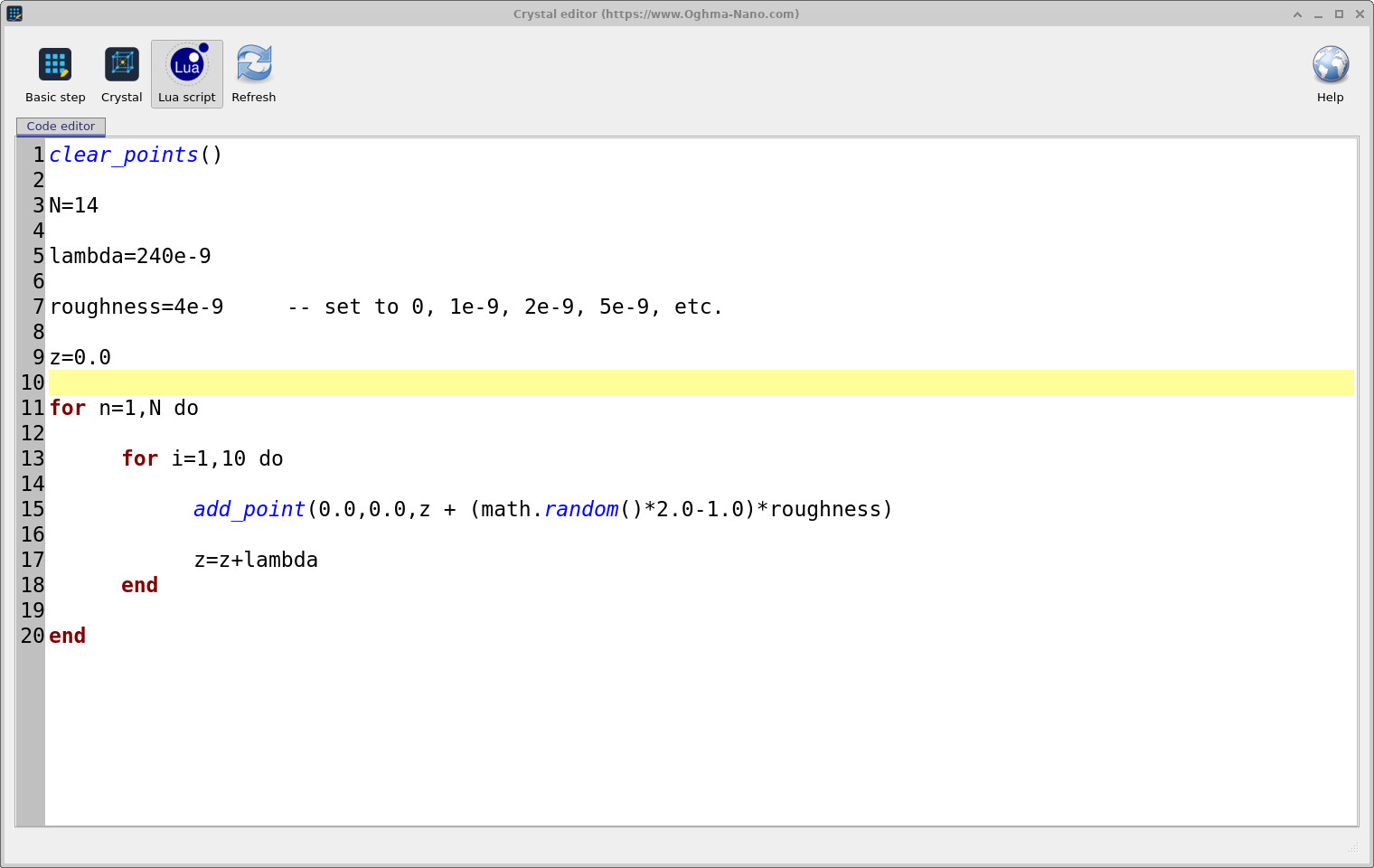
A simple example — placing objects at equally spaced positions along z with a small random roughness applied to each position — is shown below. This is useful for modelling fabrication disorder in grating structures:
clear_points()

N = 14
lambda = 240e-9
roughness = 4e-9    -- set to 0, 1e-9, 2e-9, 5e-9, etc.

z = 0.0

for n = 1, N do
    for i = 1, 10 do
        add_point(0.0, 0.0, z + (math.random() * 2.0 - 1.0) * roughness)
        z = z + lambda
    end
end
6. Example: hexagonal lattice
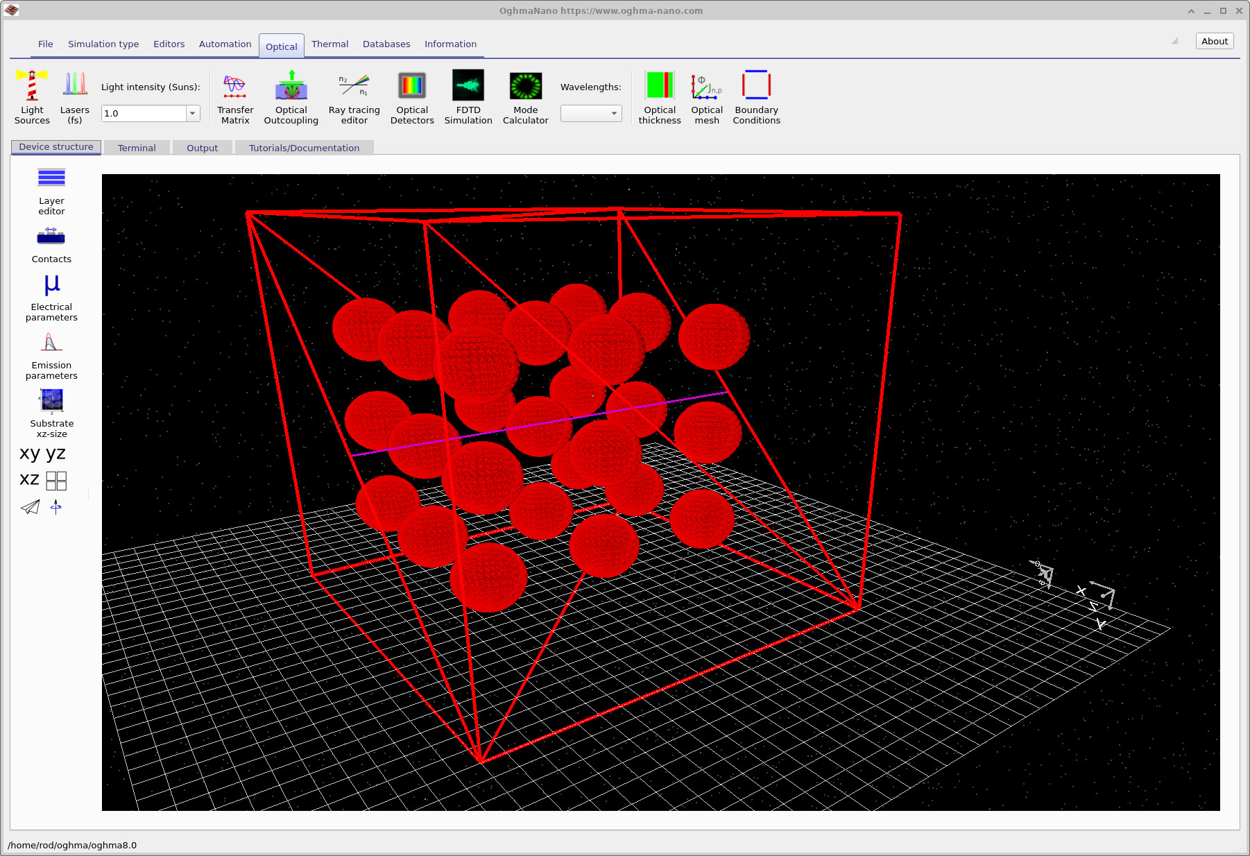
A practical example of the crystal mode is the construction of a hexagonal lattice, as might be used for a photonic crystal or a hexagonally packed array of nanopillars. The lattice editor configuration is shown in ?? and the resulting 3D structure in ??.
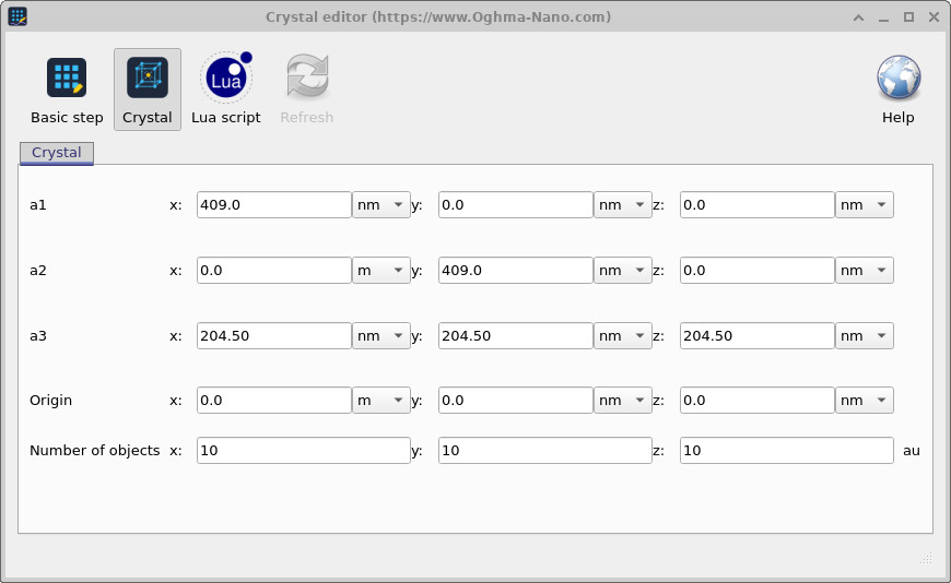
The key values are a2_x = a/2 = 1.5 µm and a2_y = a√3/2 = 2.598 µm, which together give the 60° angle between a1 and a2 that defines hexagonal symmetry. The out-of-plane vector a3 is simply the layer-to-layer repeat distance along z.
7. Example: double helix using Lua scripting
A more visually complex example of what the Lua scripting mode can produce is a double helix — two interleaved helical strands winding around a common axis. This geometry cannot be expressed as a Bravais lattice and requires the scripting interface. The Lua code is shown in ?? and the resulting structure in ??.
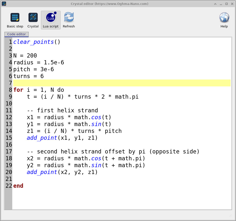
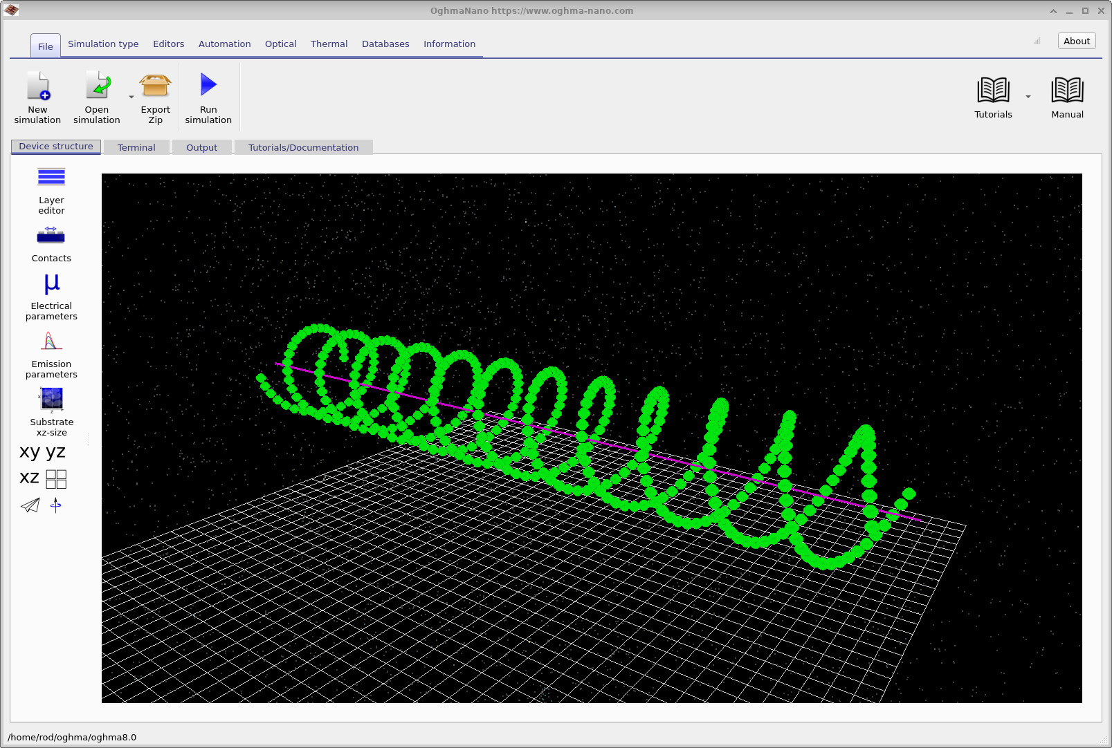
The complete Lua script for this structure is:
clear_points()

N = 200
radius = 1.5e-6
pitch = 3e-6
turns = 6

for i = 1, N do
    t = (i / N) * turns * 2 * math.pi

    -- first helix strand
    x1 = radius * math.cos(t)
    y1 = radius * math.sin(t)
    z1 = (i / N) * turns * pitch
    add_point(x1, y1, z1)

    -- second helix strand offset by pi (opposite side)
    x2 = radius * math.cos(t + math.pi)
    y2 = radius * math.sin(t + math.pi)
    add_point(x2, y2, z1)

end
Each strand is traced by stepping the parameter t from 0 to 2π × turns. The x and y coordinates follow a circle of the given radius, while z increases linearly with t at the specified pitch. The second strand is offset by π radians — placing it on the opposite side of the helix axis at each point — which produces the characteristic interleaved double-helix geometry.
8. Summary
The step editor in OghmaNano provides three complementary methods for placing objects periodically in 3D space. Basic step mode handles simple uniform arrays with a single displacement vector. Crystal mode supports any Bravais lattice through three primitive vectors a1, a2, a3, enabling hexagonal, cubic, or custom non-orthogonal arrangements. Lua scripting mode removes all geometric constraints, allowing points to be placed at arbitrary coordinates computed from any mathematical expression — as illustrated by the double helix example above. In all three modes, every copy of the object inherits the same optical and electrical properties as the original, so the entire periodic structure can be modified by editing a single object.