Ray-Tracing Tutorial (Part D): Adding Shapes and Materials
In the previous parts you worked with objects that were already set up for you: two prisms, a lens, an aperture and a detector. In this part you will add a completely new object to the scene. This involves two steps:
- Defining the mesh (the 3D shape used for ray tracing).
- Selecting the optical material from which the shape is made.
We will create a new free object, enable a complex mesh taken from the shape database, and then replace the default box with a classic ray-tracing shape: the teapot.
Step 1: Create a new free object
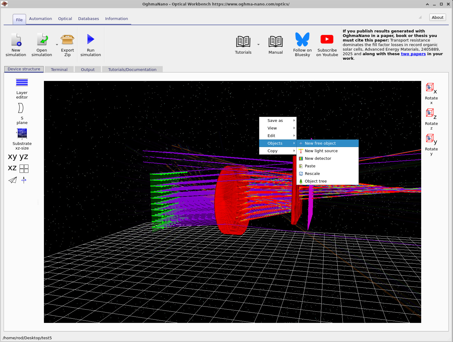
Start from the scene you finished in Part C (lens, aperture and detector in place). To add a new object:
- Right-click on an empty region of the floor grid (make sure you are not clicking on an object).
- From the context menu select Objects → New free object, as shown in ??.
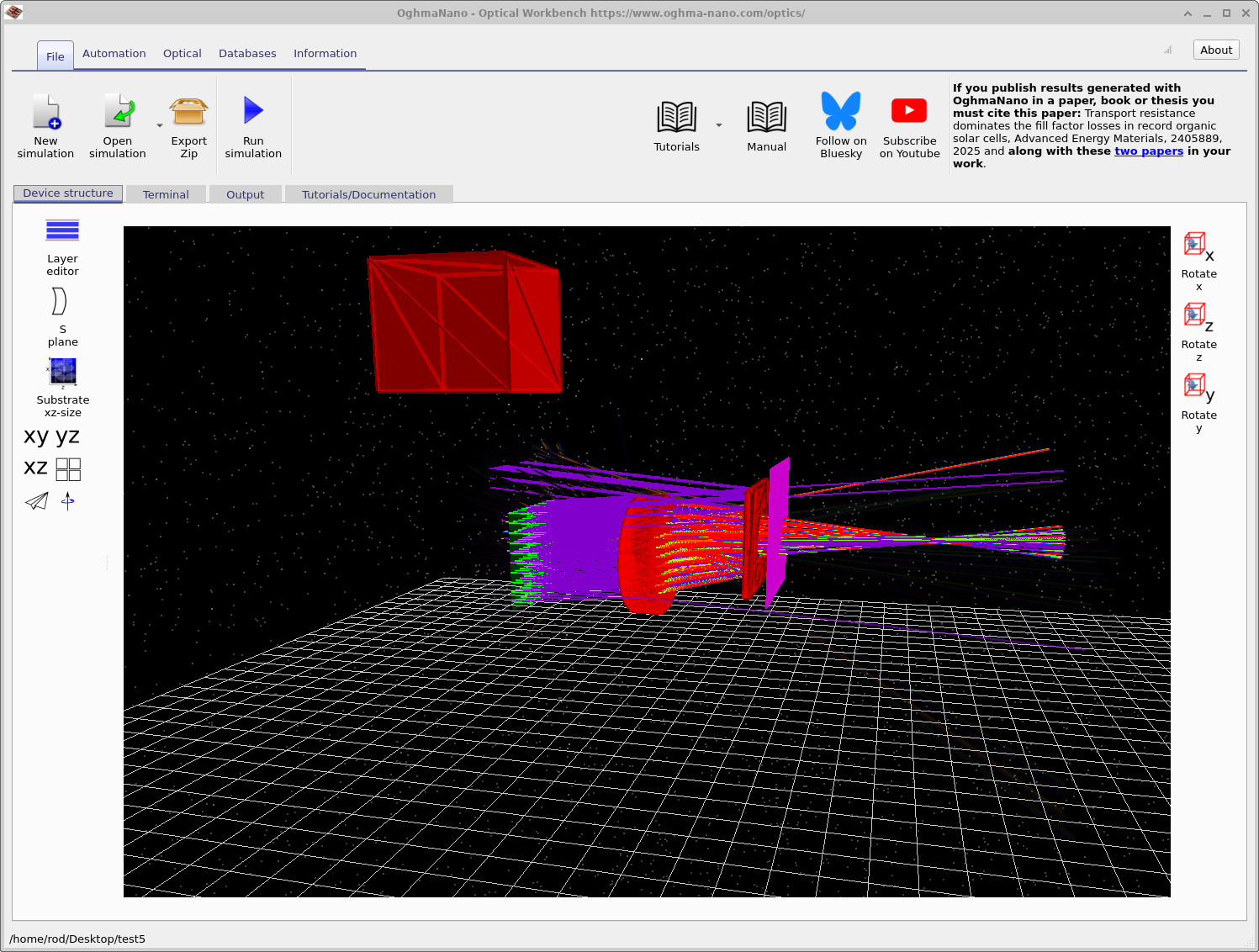
- A new box-shaped object will appear in the scene, as in ??. You may need to zoom out slightly to see it.
Step 2: Enable a complex mesh
New free objects start with a simple box mesh. To use one of the more complex shapes from the database (such as the teapot), you must first enable a complex mesh:
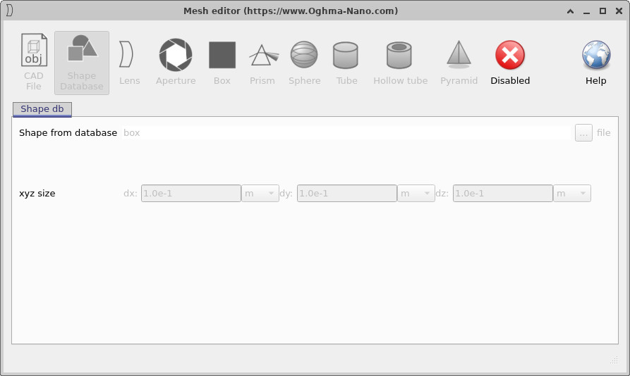
- Right-click the new box and choose Mesh editor, as in ??.
- The mesh editor will open. At first the mesh is disabled – this means the object uses the simple box geometry only.
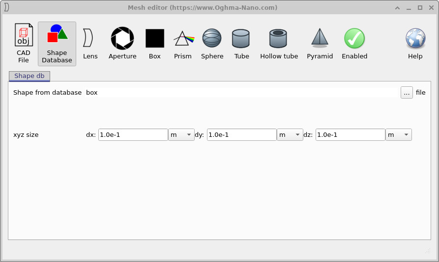
- Click the Disabled button to enable a complex mesh. The panel now shows a Shape Database entry with box selected, as in ??.
At this stage the object has a full mesh representation, but we are still using a box. In the next step we will swap the shape for a teapot.
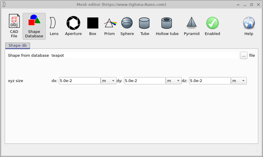
Step 3: Load the teapot from the Shape database
In the mesh editor, stay on the Shape Database tab. We now choose the teapot and set its size:
- Set the xyz size fields to
dx = 5.0e-2 m,dy = 5.0e-2 m,dz = 5.0e-2 mas in ??. This keeps the teapot small enough to fit comfortably in the scene. - Click the ... button next to Shape from database. This opens the shape browser shown in ??.
- Double-click teapot to select it.
- Close the mesh editor.

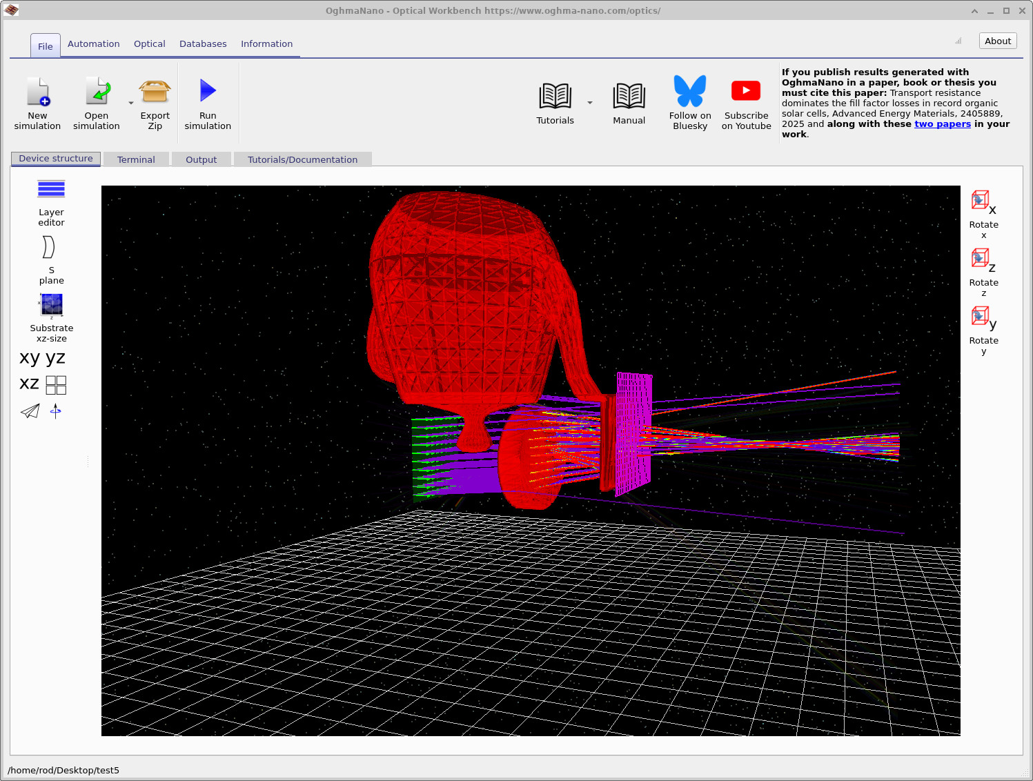
When you close the mesh editor, the scene should now contain a teapot-shaped object instead of the original box, similar to ??.
Step 4: Set the optical material
The mesh defines only the geometry. To complete the object you also need to select the material from which the teapot is made:
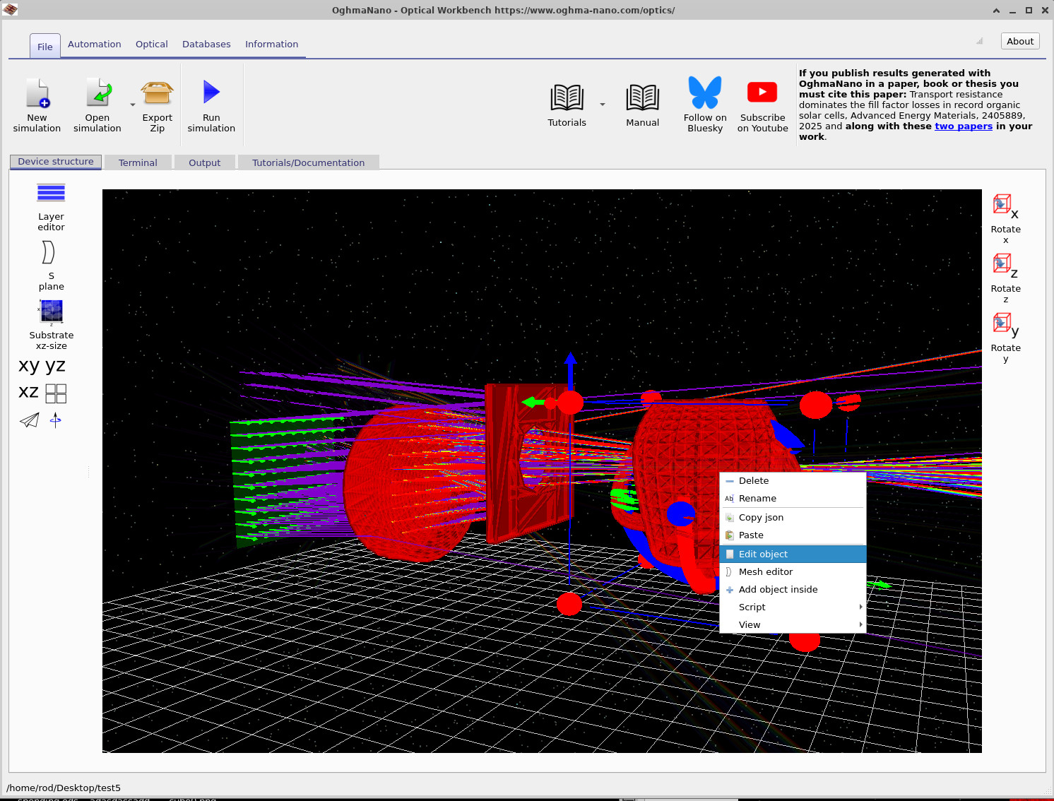
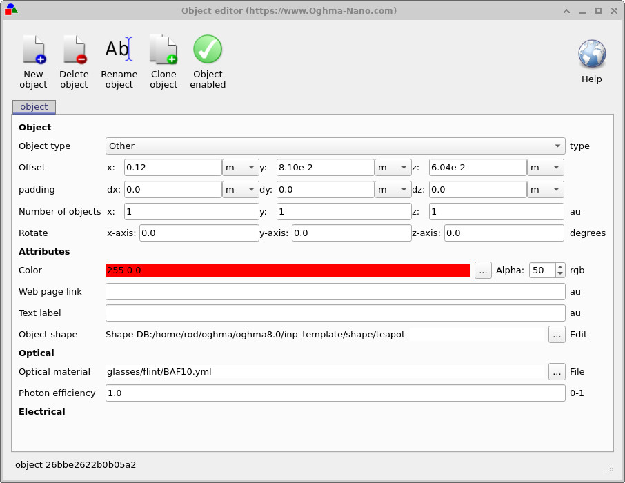
- Right-click the teapot and choose Edit object, as in ??.
- In the object editor, under Optical material, choose a suitable glass from the material database (for example glasses/flint/BAF10.yml), as in ??.
- Optionally adjust the Alpha value to change how transparent the teapot appears in the 3D view.
- Click the green tick icon to close the object editor.
Step 5: Position the teapot and run the simulation
Finally, move the teapot into the beam and run the ray tracer:
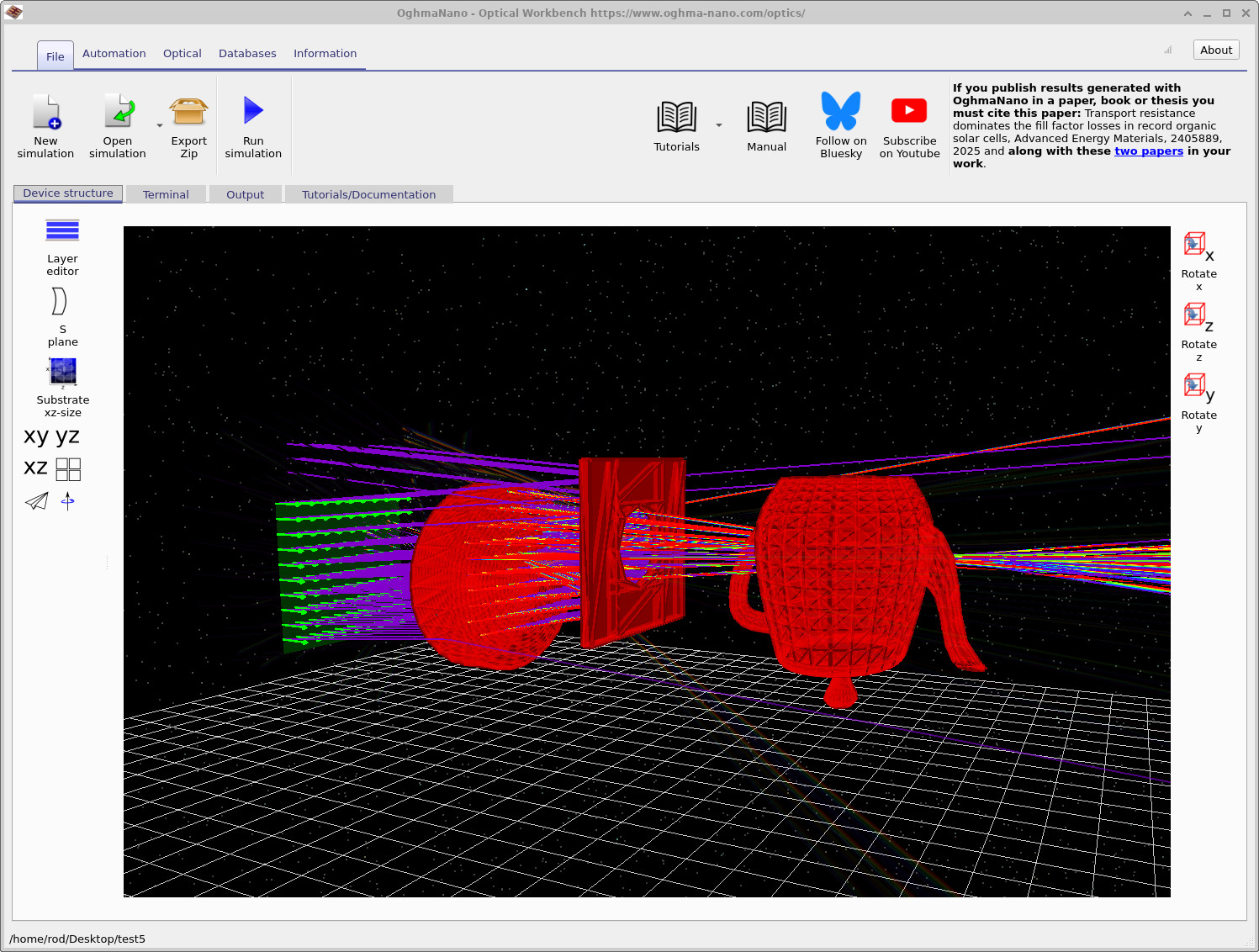
- Drag the teapot using the left mouse button until it sits in the optical path between the lens and the detector, as in ??.
- If collision detection stops it moving through other objects, hold Shift while dragging to force the move.
- Click Run simulation (or press F9) to re-trace the rays with the teapot in place.
You should now see rays passing through and around the teapot, scattering onto the detector. Try rotating the camera to view caustics and shadow regions formed by the teapot. You can also repeat the steps from Part C to inspect the updated detector image and efficiency.
👉 Next step: Continue to Part E to learn learn about changing materials and how to set the world size.