Ray-Tracing Tutorial (Part B): Editing Prisms and Lenses
In Part A you loaded the prism demo, ran the ray tracer and inspected the detector outputs. In this part you will start to manipulate the geometry: first by resizing a prism, and then by replacing the front prism with a proper lens. Along the way you will see how the Mesh editor and Object editor work together.
OghmaNano’s mesh system uses a mixture of procedural primitives (box, prism, sphere, lens, etc.) and imported CAD files. Primitive shapes are generated on-the-fly by the software and are very fast to calculate; CAD meshes are read from disk. In this tutorial we will only use primitives.
Step 1: Resize the prism using the Mesh editor
Make sure you have the prism demo scene open, as in Part A. We will first change the size of one of the prisms.
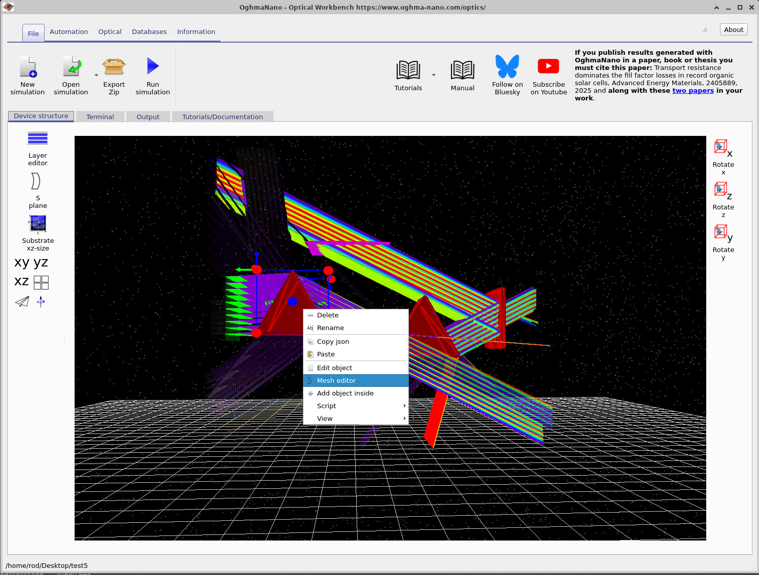
- Right-click the pyramid/prism object in the scene.
- From the context menu select Mesh editor, as shown in ??.
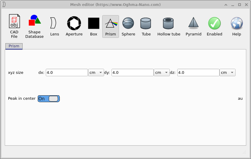
The Mesh editor opens with the current shape selected. In this case the Prism tab is active. We will shrink the prism in the x direction.
- Under xyz size, set
dxfrom4.0 cmto2.0 cm, as in ??. - Leave
dyanddzat4.0 cm. - Ensure Peak in center is switched On.
- Close the Mesh editor.

dx from 4.0 cm to 2.0 cm. The update is applied
immediately to the object in the scene.
Now click Run simulation (or press F9) and compare the new ray paths with the original ones from Part A. You should see that the narrower prism changes the way the rays are refracted and how they fill the detector.
Step 2: Replace the prism with a lens
Next you will convert the object into a proper lens. We again start from the Mesh editor, but this time switch shape type.
- Right-click the same object and choose Mesh editor again.
- In the toolbar at the top of the Mesh editor click the Lens icon, as shown in ??.

Set the lens parameters as follows:
- Surface 0 – Lens type:
Spherical - Surface 0 – Direction: On
- Surface 1 – Lens type:
Spherical - Surface 1 – Direction: On
- Body – ct:
1.0e-2 m - Body – Diameter:
0.05 m - Body – Hole diameter:
0.0 m(solid lens)
These values give a compact lens that fits easily between the source and detector. Close the Mesh editor. Back in the main window you should see that the previous prism has been replaced by a lens, but it may not yet be aligned with the optical axis.
Step 3: Rotate the lens using the Object editor
The general Object editor controls the position, rotation, colour and material of any object. We will use it to rotate the lens so that its axis lines up with the incoming rays.
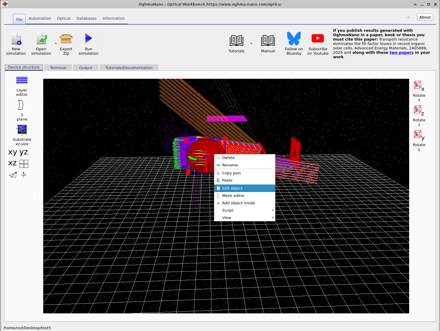
- Right-click the lens and select Edit object, as in ??.
- In the Object editor set the rotation to:
- x-axis:
90.0degrees - y-axis:
90.0degrees - z-axis:
0.0degrees
- x-axis:
- Close the Object editor.
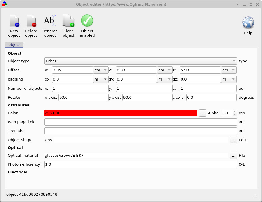
90.0 degrees so that the lens faces the source.
After closing the editor the lens should now sit correctly in the optical path. If its position is slightly off, you can drag it with the mouse to fine-tune its location between the source, prisms and aperture.
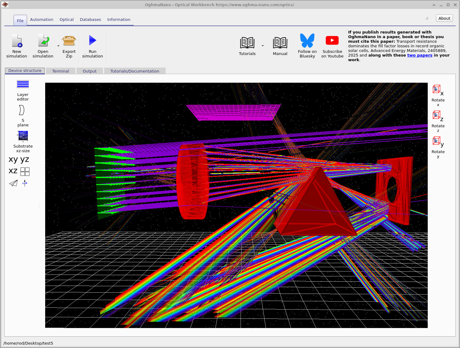
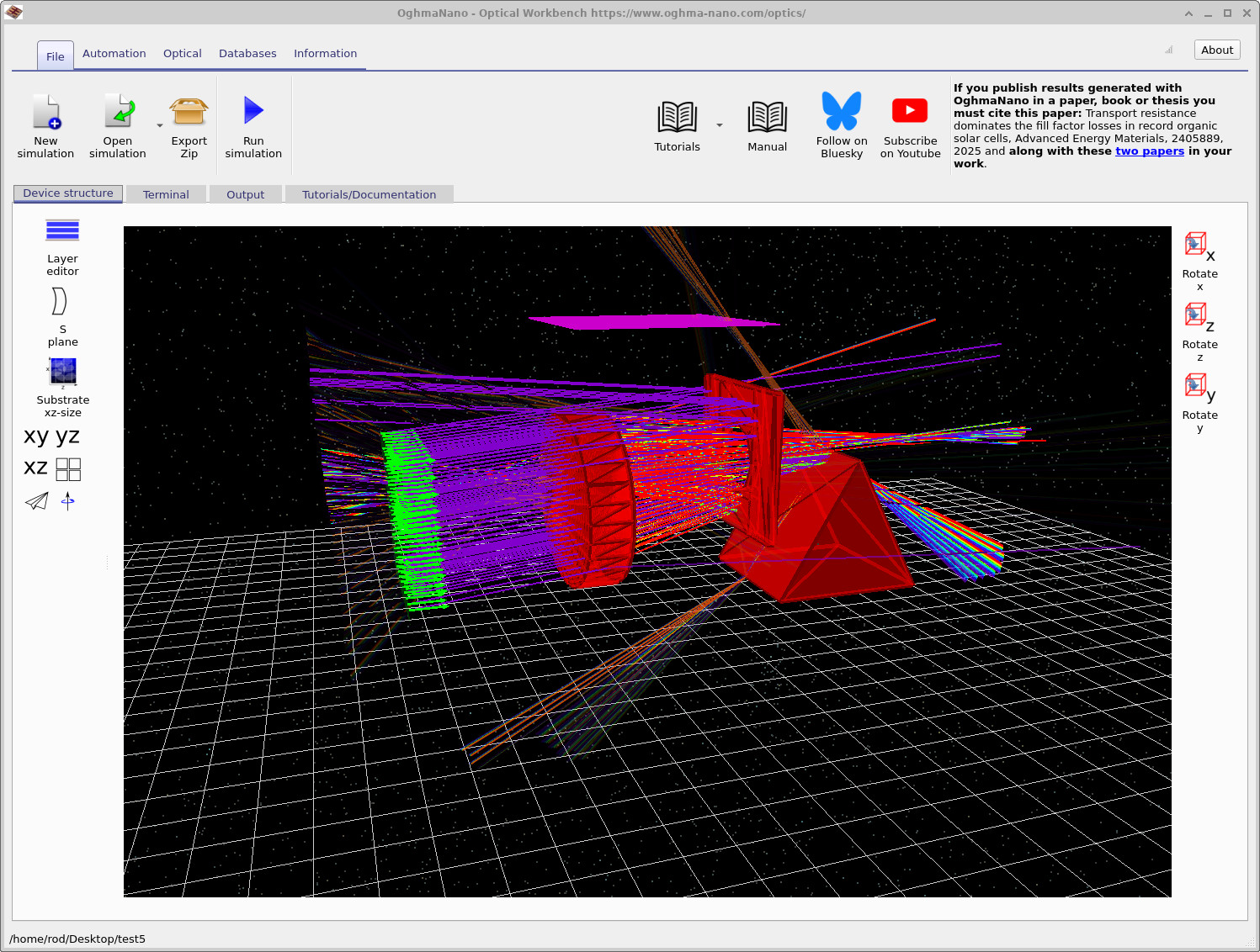
Run the simulation again. The scene should now look similar to ??, with the lens focusing and redistributing the coloured rays.
Step 4: Move the aperture and use collision detection
Finally we will adjust the position of the aperture (the red plate with a hole). This lets you experiment with beam clipping and the “hole” in the detector image.
- In the 3D view, drag the aperture with the mouse to move it towards the lens.
- You will notice that as you drag it, the aperture collides with other objects and cannot pass through them – OghmaNano prevents objects from overlapping by default.
- To force the aperture through another object, hold Shift while dragging. This temporarily disables collision detection.
- Place the aperture close to the lens, as in ??.
- Run the simulation again and observe how the beam profile and detector outputs change.
If any object becomes stuck against another, remember you can always use Shift+drag to move it freely. This is particularly useful when you have a crowded scene with many overlapping rays and optical elements.
👉 Next step: Continue to Part C to analyse detector images and beam profiles in more detail, and to explore how these outputs relate to your optical design choices. For an overview of optical systems and ray-tracing simulations, see Optical systems and ray tracing overview.