Contact editor
1. Overview
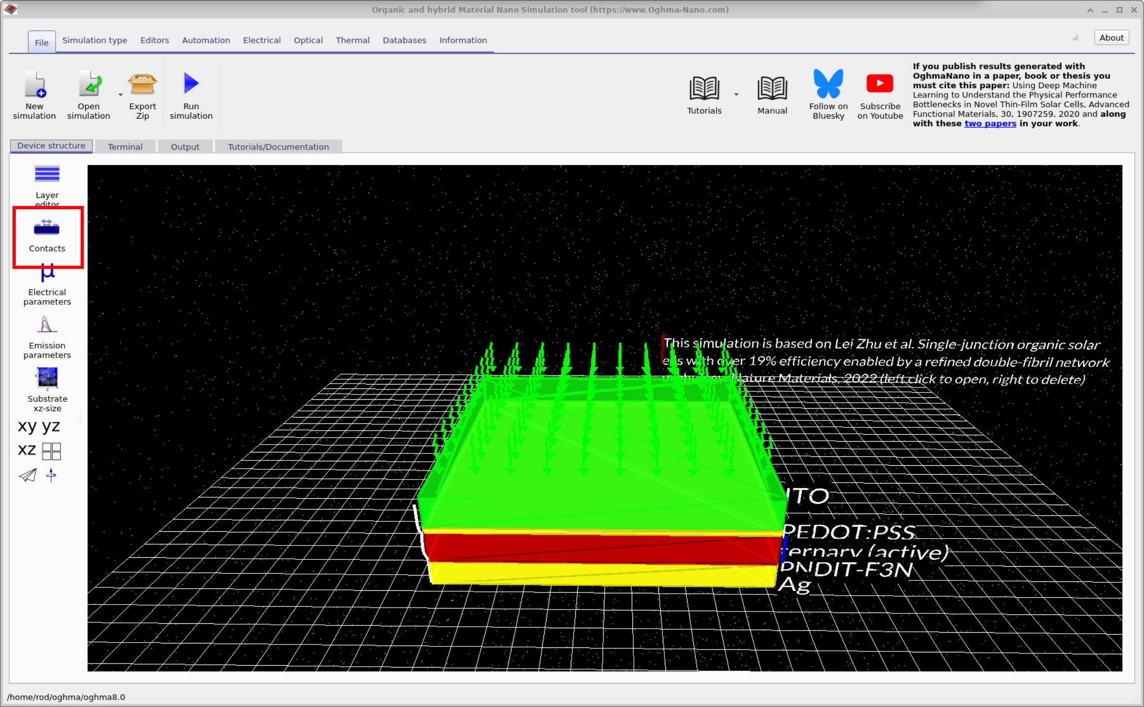
The Contact editor is used for defining contacts. Contacts are part of the electrical model and determine how charge is injected into, or removed from, the device. With this editor you set the contact’s position, give it a name, specify how voltage is applied (and the value), and define the relevant carrier densities and physical model at the contact. This manual page gives you an overview of those settings.
To open the editor, go to the main window, select the Device tab, and click the Contacts button (??). This opens ??, which is the main Contact editor window.
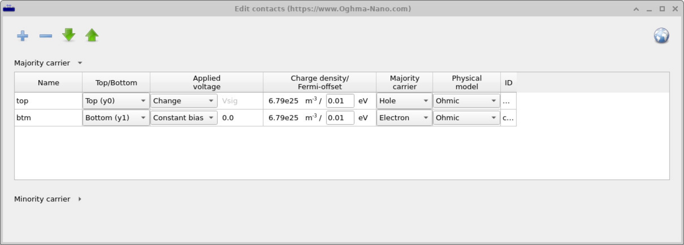
Contact editor columns
- Name: An English name for the contact. This can be set to any label (e.g. top, gate, collector).
-
Top/Bottom: The position of the contact. Options include
Top (y0),Bottom (y1),Left (x0),Right (x1),Front (z0),Back (z1), or simplyX,Y,Z.
These denote the coordinate location of the contact. - Left/right contacts are often used for side-injecting transistor geometries. - Top/bottom contacts are typical for planar devices such as OLEDs or solar cells. -X/Y/Zcontacts allow injection into a specific point in the device, often used for large-area device modelling. -
Applied voltage: Defines how voltage is applied to the contact.
Options:
- Constant bias: Holds the contact at a fixed potential, which can be nonzero. Useful in multi-terminal devices where one terminal is fixed at a set voltage.
- Change: The simulation sweep voltage is applied to this contact (e.g. for J–V curve simulations).
- Ground: Sets the contact to 0 V reference.
-
Charge density / Fermi offset: defines the equilibrium carrier
density at the contact, according to Maxwell–Boltzmann statistics:
\( n = N_c \exp\left(-\frac{E_c - E_f}{kT}\right) \),
\( p = N_v \exp\left(-\frac{E_f - E_v}{kT}\right) \).
The charge density should be lower than the effective density of states set in the electrical editor. The Fermi offset denotes how far the contact Fermi level is from the band edge. Normally this is a positive number (within the band). Negative values should only be used in exceptional circumstances.
Note: The JSON file stores the actual carrier density; the Fermi offset is calculated for user convenience. - Majority carrier: specifies whether the contact injects holes or electrons as the dominant carrier.
-
Physical model: Describes the electrical behaviour of the contact:
- Ohmic: ideal, fully conducting contact.
- Fully blocking: no charge transfer through the contact.
- Ohmic + barrier: ohmic but with a shallow injection barrier implemented via a boundary mesh point. Useful for simulating S-shaped J–V curves.
- Schottky: non-ohmic, rectifying barrier contact.
- ID: Hidden column containing the JSON identifier for the contact. This is used in scripting and automation.
Minority carrier settings
Click the Minority carrier drop-down arrow to reveal the Minority-carrier table. By default, the top part of the Contact editor focuses on the Majority carrier settings and assumes the Minority carrier will be handled automatically (i.e., complementary to the majority choice).
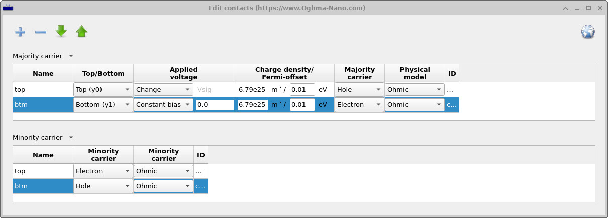
The carrier pairing is fixed by physics: if the majority carrier is hole, the minority carrier is electron; if the majority is electron, the minority is hole. What you can choose, however, are the boundary conditions applied to the minority carrier at each contact (via the physical model).
- Ohmic (for both carriers): Appropriate for devices where both carriers are well injected/extracted—for example many laser diodes (e.g., GaAs) with highly conducting contacts.
- Selective/Blocking behaviour: Common in solar cells. You might set the majority carrier to Ohmic (to extract it efficiently) while making the Minority carrier at the same electrode Fully blocking (to suppress recombination). Variants such as Ohmic + barrier or a Schottky model let you tune partial selectivity.
In practice, for solar cells, introducing minority-carrier blocking at the “wrong” carrier contact often improves selectivity and can increase the open-circuit voltage VOC by roughly 0.1–0.2 V, depending on the device and how the boundaries are configured. Use the Minority-carrier table to set these boundary conditions explicitly.