Emission editor
1. Overview
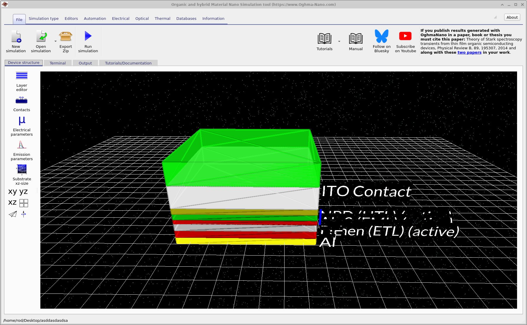
The Emission editor allows you to control how light is generated within active layers of your device, both for photoluminescence (PL) and electroluminescence (EL). Only electrically active layers can emit light. Open the editor by clicking Emission parameters in the left-hand menu of the Device structure tab. You can then enable or disable emission for each active layer using the toggle at the top left of the editor window.
2. Parameters
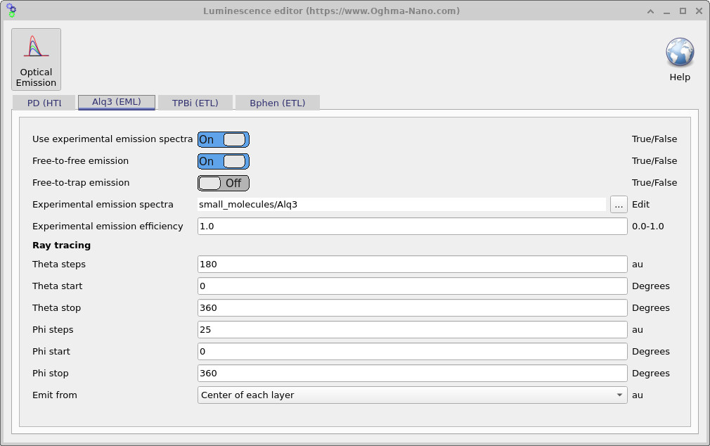
When emission is enabled, the following options are available:
- Use experimental emission spectra — if enabled, the emission spectrum is taken directly from the Materials database. A valid spectrum must exist for the selected material. Many common materials already include measured spectra.
- Free-to-free emission — toggles whether band-to-band recombination generates photons. On means recombination produces light; Off means recombination is dark.
- Free-to-trap emission — sets whether free-to-trap recombination contributes to light emission. On generates photons; Off means these events are dark.
- Experimental emission spectrum — path/name of the emission spectrum file in the database (read-only unless edited manually).
- Experimental emission efficiency — efficiency factor (0.0–1.0) for photon generation. A value of 1.0 means every recombination event produces a photon; 0.5 means only half of events do.
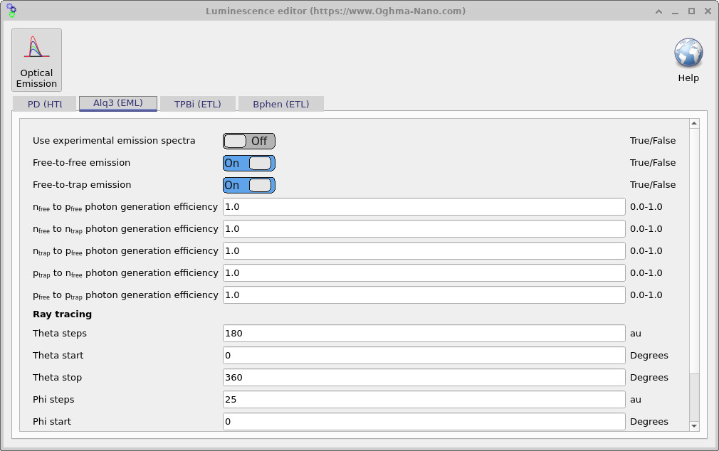
If Use experimental emission spectra is disabled, additional fields appear to let you specify photon generation efficiencies for different recombination/trapping channels:
- nfree → pfree photon generation efficiency
- nfree → ntrap photon generation efficiency
- ntrap → pfree photon generation efficiency
- ptrap → nfree photon generation efficiency
- pfree → ptrap photon generation efficiency
Each value ranges from 0.0–1.0 and specifies the fraction of recombination events that produce photons. This allows modelling of more complex radiative and non-radiative recombination pathways, e.g. trap-mediated emission relevant in infrared or defect spectroscopy.
3. Ray tracing
The bottom section configures angular sampling for ray tracing of emitted photons:
- Theta steps / Theta start / Theta stop — number of angular slices in the polar direction (degrees).
- Phi steps / Phi start / Phi stop — number of angular slices in the azimuthal direction (degrees).
- Emit from — sets the emission origin within the layer (e.g., center of each layer).
Together, these parameters define the angular distribution of rays sampled on a sphere around the emitting layer. For example, with 180 theta steps (0–360°) and 25 phi steps (0–360°), the simulation samples a full spherical distribution of emission directions.