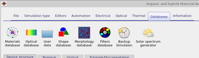
Optical filters database
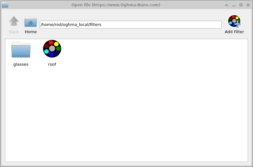
The ?? shows the Databases ribbon. By selecting the Filters database, you open the optical filters directory shown in ??. Any filters that are pre-installed or created by the user will appear in this list.
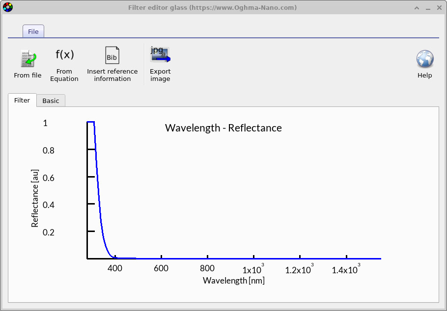
Double-clicking on the glasses entry opens one of the glass filters, as shown in ??. The curve shows the apparent reflectance of glass, which increases sharply below about 400 nm. In practice, glass attenuates light at these shorter wavelengths—some of it is reflected, while the rest is absorbed—so the light never reaches the device. OghmaNano represents this attenuation as a reflectance spectrum, making it straightforward to model how the filter blocks low-wavelength light. By applying the filter in front of a device, or multiplying it with an optical spectrum, you can exclude specific regions of the spectrum from your simulation.
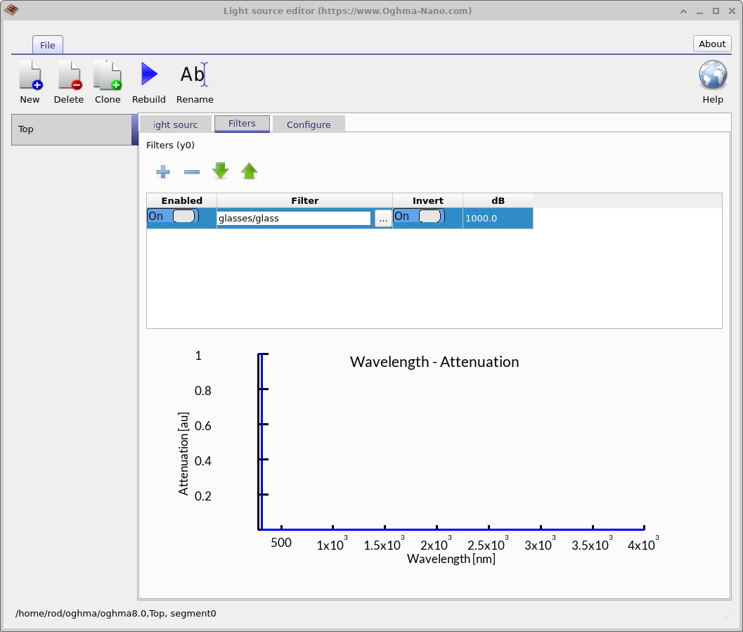
The ?? illustrates the use of this filter within the Light source editor. Here, the filter is applied to remove low-wavelength light from the source spectrum. Within this editor, you can also adjust the attenuation in decibels (dB) or invert the filter response, effectively reversing its effect. This makes it straightforward to incorporate reflectance or transmission characteristics into your optical simulations by directly multiplying them with the light source spectra.