

Interface editor
1. Overview
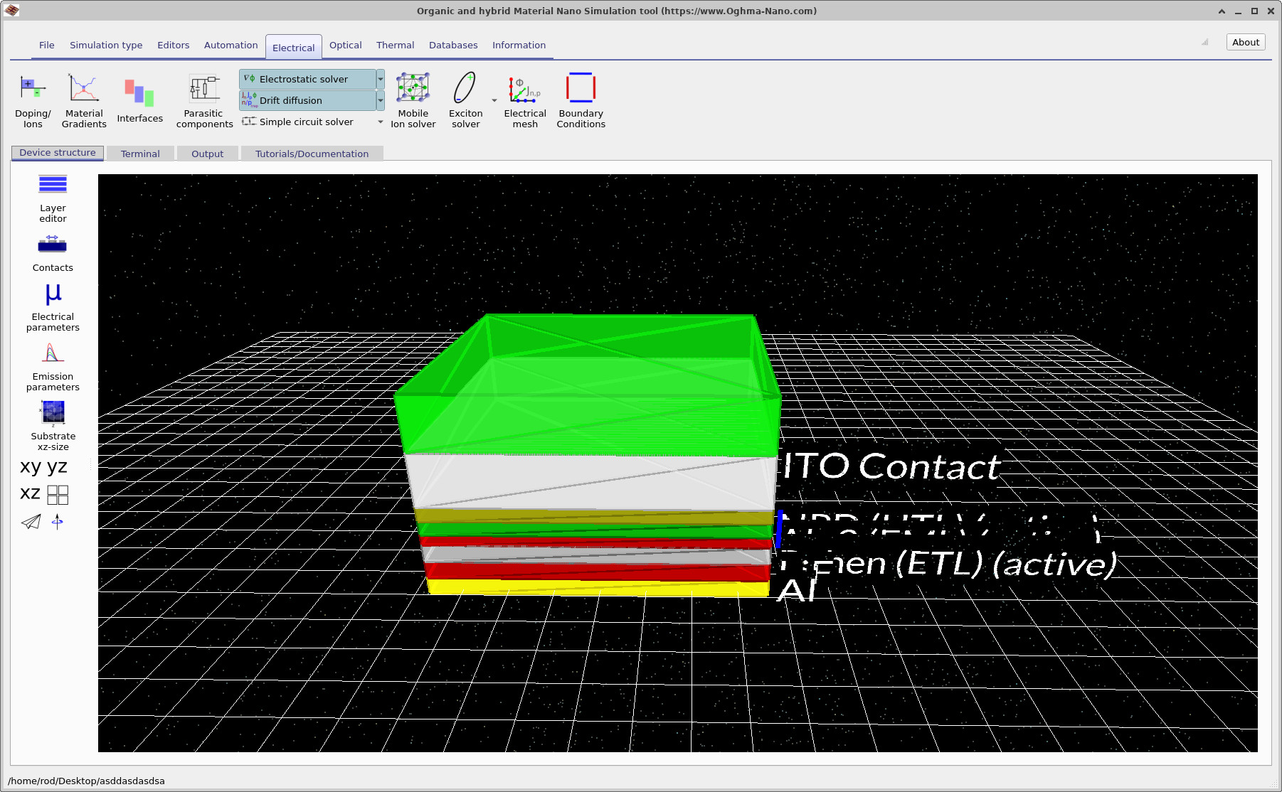
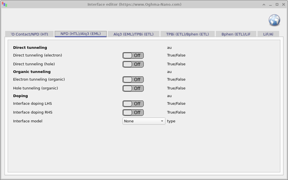
The Interface editor controls electronic transport phenomena that occur at material boundaries. Interfaces are automatically listed for each pair of adjacent layers in the device structure. By default, charge carriers can drift and diffuse across interfaces according to the gradient of the conduction or valence bands: carriers moving uphill in energy encounter barriers and cross less easily, whereas carriers moving downhill in energy pass readily. The Interface editor adds to this baseline drift–diffusion model by introducing extra transport mechanisms that can, for example, assist otherwise difficult uphill transitions. Open the editor by clicking the Interfaces icon (red, green, blue bars) in the Electrical ribbon.
2. Parameters
- Direct tunneling (electron / hole) — enables direct quantum tunneling of carriers through the interface barrier. Based on the model described in the theory section: \[ J = A(n-n^{eq})V \exp\left(-B\sqrt{\phi}\right), \] where \(A\) has units of m·s\(^{-1}\)·V\(^{-1}\), \(B\) is dimensionless (fit parameter), \(\phi\) is the barrier height, \(V\) the applied bias, and \(d\) the interface thickness. Separate toggles exist for electrons and holes, each with its own A/B values.
- Organic tunneling — a special case applicable at organic heterojunctions, where carriers drift into interface-localized trap states. As described in the theory section, the tunneling current is expressed as: \[ J_p = q T_{h}\left((p_{1}-p_{1}^{eq})-(p_{0}-p_{0}^{eq})\right), \] for holes, and \[ J_n = -q T_{e}\left((n_{1}-n_{1}^{eq})-(n_{0}-n_{0}^{eq})\right), \] for electrons, where \(T_h\) and \(T_e\) are rate constants set via the editor toggles.
- Interface doping (LHS/RHS) — applies a sheet of charge one mesh-point thick to either the left-hand side (LHS) or right-hand side (RHS) of the interface. Values can be positive or negative, allowing simulation of interfacial charge accumulation or depletion. This is useful for modelling trapped charge at boundaries or threshold-voltage shifts in OFETs.
3. SRH interface traps
OghmaNano includes Shockley–Read–Hall (SRH) recombination through trap states located at material interfaces. Interface traps are specified as a sheet density \(N_t\) in units of m-2.
The recombination rate is calculated using the standard SRH expression:
\[ R_{\mathrm{SRH}} = \frac{np-n_{\mathrm{eq}}p_{\mathrm{eq}}} {\tau_p(n+n_1)+\tau_n(p+p_1)}, \]where \(n\) and \(p\) are the local electron and hole concentrations, \(n_{\mathrm{eq}}\) and \(p_{\mathrm{eq}}\) are the corresponding equilibrium concentrations, and \(n_1\) and \(p_1\) describe the energetic position of the trap state.
The electron and hole capture lifetimes are:
\[ \tau_n = \frac{1}{\sigma_n v_{\mathrm{th},n} N_t}, \qquad \tau_p = \frac{1}{\sigma_p v_{\mathrm{th},p} N_t}, \]where \(\sigma_n\) and \(\sigma_p\) are the electron and hole capture cross sections and \(v_{\mathrm{th},n}\) and \(v_{\mathrm{th},p}\) are the corresponding thermal velocities.
The interface trap density is distributed equally across the two mesh points adjacent to the material boundary. For left- and right-hand mesh spacings \(\Delta x_L\) and \(\Delta x_R\), the corresponding local trap densities are:
\[ N_{t,L} = \frac{N_{t,\mathrm{interface}}}{2\Delta x_L}, \qquad N_{t,R} = \frac{N_{t,\mathrm{interface}}}{2\Delta x_R}. \]This gives:
\[ N_{t,L}\Delta x_L + N_{t,R}\Delta x_R = N_{t,\mathrm{interface}}. \]The SRH recombination rate is evaluated on both sides of the interface using the local carrier concentrations and material parameters.
The trap energy is specified relative to the centre of the local band gap:
\[ E_t = \frac{E_g}{2} + \Delta E_t, \]where \(\Delta E_t\) is the value entered in the Et (relative to Eg/2) field. The auxiliary SRH carrier concentrations are:
\[ n_1 = n_i \exp\left( \frac{q(E_t-E_g/2)}{k_B T} \right), \qquad p_1 = n_i \exp\left( \frac{q(E_g/2-E_t)}{k_B T} \right). \]The parameters in the Equilibrium SRH traps section of the Interface editor are:
- SRH interface traps enabled — enables or disables interface SRH recombination.
- Et (relative to Eg/2) — trap energy relative to the centre of the local band gap, in eV. A value of 0 places the trap at mid-gap.
- Nt — total interface trap density in m-2.
- σn — electron capture cross section in m2.
- σp — hole capture cross section in m2.
Interface SRH recombination is used to model defect-assisted recombination at material boundaries, including semiconductor/transport-layer interfaces in solar cells, LEDs and other multilayer devices. It is particularly useful for studying interface passivation, where changes in interface trap density or capture cross section modify the non-radiative recombination rate.
4. Application in simulation
Interface processes strongly influence current transport and device characteristics:
- Tunneling dominates when barriers are thin or when trap-assisted hopping is possible at organic–organic interfaces.
- Interface doping mimics charged defect layers or intentional interface engineering, modifying local band bending and injection barriers.
By combining these mechanisms, the Interface editor allows you to capture realistic device physics in organic and hybrid heterostructures, from trap-assisted tunneling in OLEDs to interface charge effects in OFETs.