S-plane editor
Many optical design packages — such as Zemax OpticStudio, CODE V and OSLO — use an S-plane editor to describe lens systems. Here, S stands for surface: an S-plane editor is essentially a table of surfaces that light passes through, listed in the order encountered along the optical axis. Each row corresponds to a surface with a specified curvature, thickness to the next surface, diameter and material.
The same idea is used in OghmaNano’s Optical Workbench. Light is assumed to travel from left to right: it starts in air, passes through a surface of the first lens (changing refractive index), traverses the thickness of the lens, passes out through the second surface, and so on for each lens in the stack. By editing the S-plane table, you specify a complete optical system in terms of its surfaces.
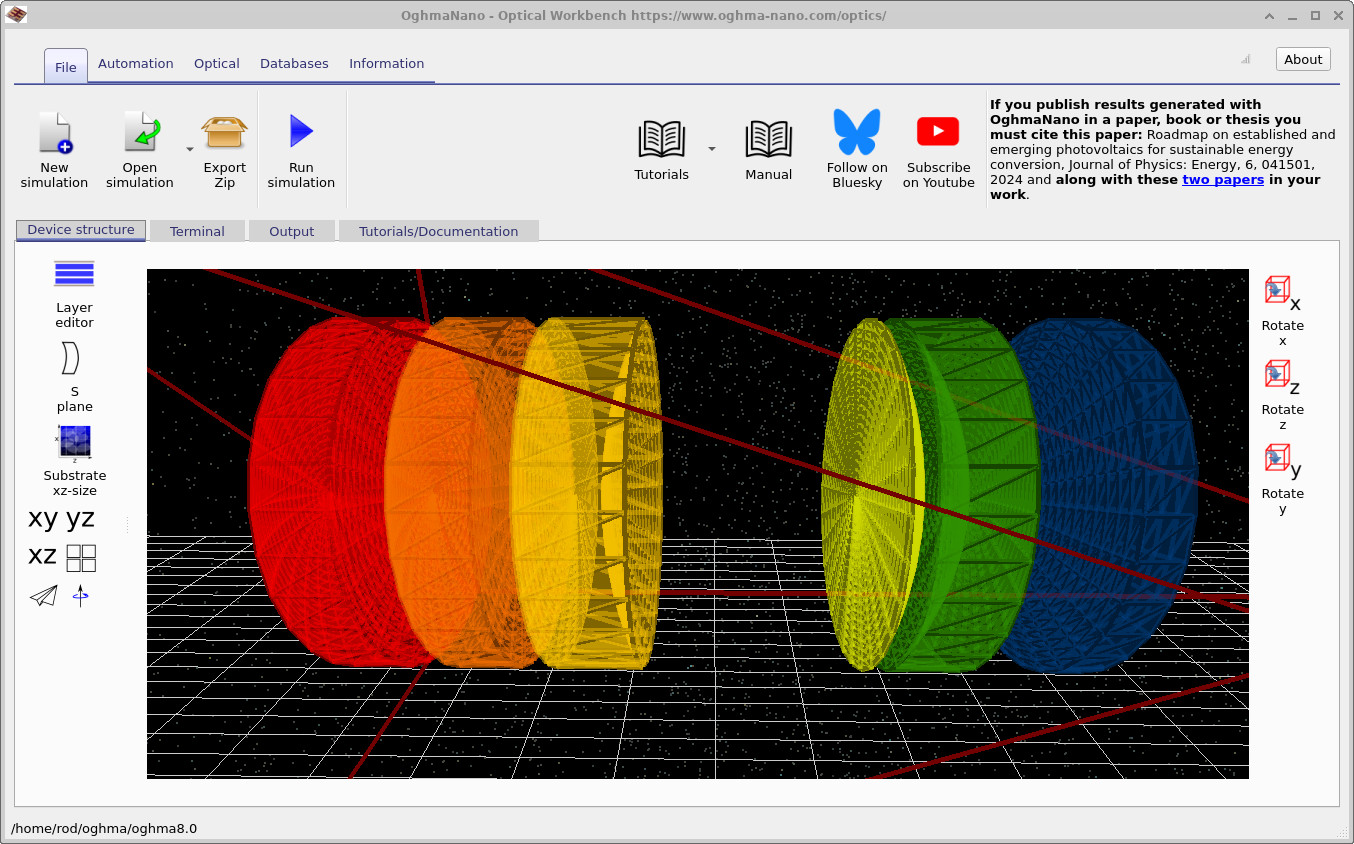
While the S-plane view is inherently one-dimensional (surfaces along an axis), OghmaNano is, by design, a fully 3D ray-tracing environment rather than a pure 1D propagation model. The S-plane editor therefore acts as a convenient, literature-standard view onto a genuinely 3D scene. Lens definitions in the S-plane table are converted into 3D lens objects which live inside the main simulation window, as seen in ??.
Accessing the S-plane editor
The S-plane editor is accessed from the Optical Workbench main window. In the Device structure tab, click the S plane icon on the left-hand toolbar (just below the Layer editor), as shown in ??. This opens the S-plane editor window, where you can create, edit and organise lens stacks.
The S-plane table
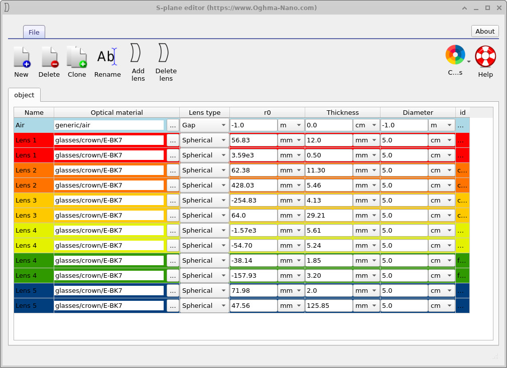
The S-plane editor presents lens systems as a table of surfaces (??). Each pair of rows corresponds to one physical lens: an input surface and an output surface. Columns capture the key optical parameters:
- Name — a label for the region (air, Lens 1, Lens 2, …).
- Optical material — refractive index model or glass designation.
- Lens type — spherical, aspheric, etc.
- Gap or Thickness — distance to the next surface.
- r0 — radius of curvature of the surface.
- Diameter — clear aperture of the surface.
- id and auxiliary columns — internal identifiers and options.
As you edit values in the S-plane table, the corresponding 3D lens geometry is updated immediately in the Optical Workbench view. Colours are used consistently so that, for example, the red rows labelled Lens 1 correspond to the red lens in the 3D scene, the orange rows to the orange lens, and so on.
Lens groups and 3D placement
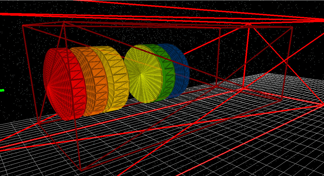
In OghmaNano, each S-plane table is associated with a 3D object called a lens group. A lens group is simply a container that holds all the lenses belonging to a particular S-plane definition. In the 3D view the lens group appears as a red bounding box, as shown in ??. The outer red box represents the global simulation volume; the inner red box is the lens group. When you move the lens group in 3D — for example by clicking and dragging it while holding Shift — all lenses defined in the corresponding S-plane table move together. This makes it easy to reposition an entire optical assembly within a larger scene.
Clicking New in the S-plane editor creates a new lens group with its own S-plane table. You can therefore have multiple independent S-planes within a single simulation, each sitting in its own 3D lens group. This is useful for modelling compound optical systems such as telescopes with separate objective and eyepiece assemblies, or camera modules with multiple lens blocks.
S-plane view vs 3D world
It is important to emphasise that, in OghmaNano, the S-plane editor is a derived view of the 3D world rather than the underlying truth. The 3D lens objects and their meshes are the primary representation used by the ray tracer. The S-plane table is a structured, surface-by-surface description extracted from these objects and kept in sync with them.
This hybrid approach combines the best of both worlds:
- You retain a full 3D simulation environment, with lenses represented as explicit meshes that can interact with arbitrary geometry.
- At the same time, you gain a standard S-plane interface that matches how lens designs are usually presented in the optics literature and in traditional design tools.
When designing telescopes, camera lenses or other axial systems, it is often most convenient to start with the S-plane table: specify surfaces, radii and thicknesses, then inspect the resulting 3D layout. For more complex 3D optical structures, you can combine S-plane-defined lens groups with CAD-based or image-based meshes from the CAD / Mesh editor and Shape database.